
The main Modular Aerodynamic Design Computational Analysis Process (MADCAP) graphics window is subdivided into three distinct areas. Each of these areas is described in detail below. Additionally, help is provided for the various peripheral input devices. The help sections in this manual are:
Help on these functions is available below.
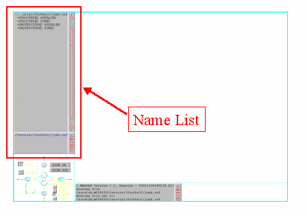
The graphics window name list is located on the left side of the main graphics window. The contents of the name list depends on the type of file that is currently set as the current display file.
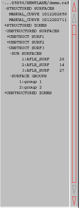
A typical graphics name list (a .csf file here), is presented below.
On the far right side of the name list are two up arrows, two down arrows, and a large vertical rectangle. These are buttons which can be used to control scrolling through the name list. Holding down the left mouse button on the lowest downward-pointing arrow will scroll the list forward one surface at a time. Clicking on the left mouse button on the other downward-pointing arrow scrolls the list forward one page at a time. Similarly, holding down the left mouse button on the highest upward-pointing arrow will scroll the list backward one surface at at time, while clicking on the other upward pointing arrow scrolls the list backward one page at a time. Clicking with the left mouse button anywhere within the rectangle will move the top of the display list to a point in the full list proportional to the vertical location of the pick in the rectangle. A horizontal line is drawn in the rectangle to indicate the relative location of the current top of the display list in the full list.
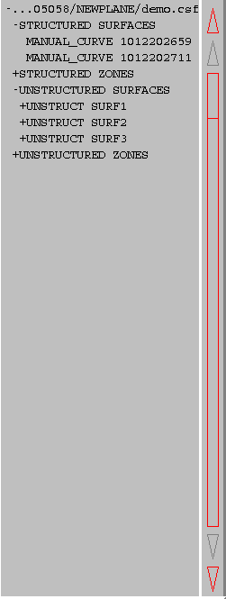
Some list items in the above example are seen to have a "+" or "-" next to them. These indicate list items which can be expanded or collapsed to show related groupings underneath. In this case, the STRUCTURED SURFACES item has been expanded, showing a list of structured surfaces contained in the grid file. List items may be expanded or collapsed by selecting them with the middle mouse button. Items may be shown on the graphics window by selecting them with the left mouse button. Selecting the item again will remove it from view. Selecting a group heading (such as UNSTRUCTURED SURFACES) with the left mouse button will display all of the objects underneath that heading.
If the Current Display File is a .cgd file, the initial name list presents the list of zones in the file. An example zone list in MADCAP is shown in the general information above.
The top line of the name list always contains the name of file currently set as the Display File. The zones are presented in numerical order. To display planes from a zone, the name is picked from the list by selecting with the middle mouse button, scrolling if necessary. An intermediate list will be presented which gives the option of accessing a list of I-planes, J-planes, K-planes or grid subsets which may be defined. When I, J, or K planes are picked, that list item is expanded to present the list of planes, as seen below.
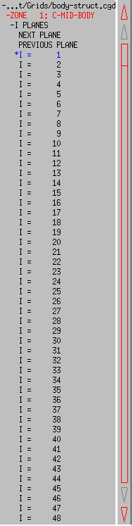
Any currently displayed planes are marked with an asterisk (*), and the names are drawn in the same color the plane itself is drawn with. To toggle a plane on or off, its name is picked from the list presented. To manually step through the grid planes, "Next Plane" and "Previous Plane" commands are available in the list. (See the Sweep Planes View menu option for a mechanism to sweep through grid planes automatically.) To define a subregion of a grid plane or a volume subset, select the "Grid Subset" list item. This will cause a new window to be displayed, as shown below.
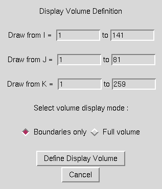
A volume subset may be selected by entering the "from" and "to" indices for the desired region. A plane may be selected by entering identical "from" and "to" indices for the desired plane. The radiobuttons at the bottom of the window are used to set whether to display only the boundaries of the specified volume or the entire volume (every grid plane in every direction). Displaying the full volume of large grids is extremely graphics-intensive and should be used sparingly. After the desired subregion has been defined, the user should pick the "OK" button, and the specified volume will be displayed and added to the name list. An example of a portion of this list is shown below.
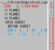
The VOL or SUB flag signifies whether the list entry is for a defined volume or subset. The indices following are the start and end indices of each computational direction on the volume or subset.
If the Current Display File is a Common Surface File (.csf), the name list contains the list of structured and unstructured surfaces and zones in the file. This list may be presented either alphabetically or chronologically depending on the setting of the Surface File Sort Mode flag in the View menus. The list is separated into Structured Surfaces, Structured Zones, Unstructured Surfaces, and Unstructured Zones. Selecting one of those items with the middle mouse button will expand the list to show the list of items of that type.
If a surface is picked from the list with the left mouse button, it is displayed on the main screen, and the name is drawn in the list in the same color as the displayed surface, and with an asterisk (*) preceding the name in the list. Selecting a zone name with the middle mouse button expands the list to show the grid planes contained in the file under the picked zone name. Selecting the zone name with the middle mouse button again will re-compress the zone list. An example of this is shown in the .cgd Files section above. Unstructured surfaces that contain sub-surfaces or surface groups can also be expanded to list the names of the sub-surface and surface groups by selecting the unstructured surface name with the middle mouse button. An example of this is shown below. Here the UNSTRUCT SURF3 unstructured surface has been expanded to see that it contains three sub-surfaces and two surface groups. The entire unstructured surface can be display by selecting the surface name with the left mouse button. A single sub-surface can be displayed by selecting the sub-surface name with the left mouse button (for instance 1:AFLR_SURF 28). Similarly a surface group can be displayed by selecting the surface group name with the left mouse button. All of the sub-surfaces can be displayed by left clicking on SUB-SURFACES and all of the surface groups can be displayed by left clicking on SURFACE GROUPS.
If the Current Display File is a ZONI3G .tmp file, the name list contains the list of non-zonal surfaces existing in the file. Like in ZONI3G, these surfaces are listed in alphabetical order. Unlike ZONI3G, however, the MADCAP user has the option of displaying the list in chronological order using the Surface File Sort Mode menu. Surfaces cannot currently be displayed from MADCAP. A conversion utility is available to convert ZONI3G .tmp files to the new Common Surface File (.csf), which is fully supported in MADCAP. The .tmp file list display may be useful in determining the contents of .tmp files while using the system's other features.
On screen access to rotation, translation, and scaling is provided at the lower left of the main graphics window. This area is shown below.
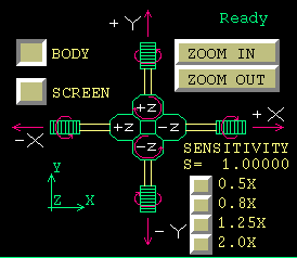
The control handle in the center of this area is used for all object rotation and translation. The arrows pointing out from the handle are used for x and y translations. Holding down the left mouse button on these arrows activates these translations. Similarly, the handles themselves perform positive and negative rotations about the x and y axes. For the z axes pointing in and out of the screen, four hexagonal buttons are provided. The rotation buttons are distinguished from the translation buttons by the circular arrow on the rotation buttons.
By default, rotations occur about the body axes. Holding down the translation or rotation handles described above rotates the geometry about the body x, y, or z axes. This typically correlates to rolling, pitching, and yawing the geometry. At times it is more desirable to rotate or translate the geometry relative to screen coordinates instead, to move the image up, down, left, or right, or to rotate the page. The BODY or SCREEN toggle in the upper left portion of this area is used to change the coordinate system the handle applies to. Note that the setting of this toggle also changes the sense of any dial and spaceball transformations.
When the SCREEN axes transformations are used, the z translation buttons cause the image to zoom in or out. Since this capability is almost always desirable even when the handle is set for body transformations, two buttons are provided in the upper right area of this screen to zoom in or zoom out when body transformations are set. Holding down the left mouse button on these buttons causes the image to zoom in or out. Either these buttons or the z translation buttons can be used to zoom the image when screen transformations are set.
A coordinate triad is displayed in the lower left portion of this screen area. The triad will have one of the following two forms depending on the setting of the Axis Mode menu option.

| 
|
The image on the left shows the triad with X, Y, Z labels, while the one on the right shows the FS, BL, WL labels. Axes pointing into the screen are drawn in yellow in "Color on BG" mode, or as a dashed line when the color mode is set to "FG on BG". The triad rotates with the geometry in real time as the geometry is rotated.
The lower right portion of the area contains a set of five toggle switches controlling the sensitivity of both the control handle and any dial and spaceball motion. There are five sensitivity levels to choose from: Normal, Double, Quad, Half, and Quarter. The default upon entry to the program is "Normal" speed, and the names of the other toggles indicate the speed relative to this default speed. The toggles are accomplished using the left mouse button.
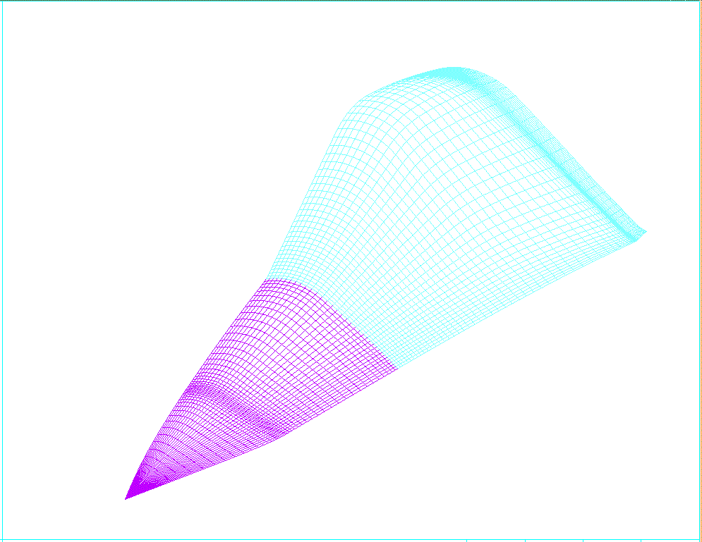
The main display area is the large region of the upper right of the main graphics window. All objects requested for display are drawn in this region. An example wireframe geometry drawn in the display area is shown below.
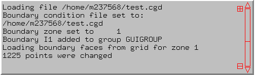
Some MADCAP operations cause informational messages to scroll to the message box located at the bottom of the screen. The message box can be interactively resized by the user by selecting the + and − boxes to the right of the message box, to a maximum of 10 lines or a minimum of 2 lines. The message can be scrolled through by using the triangles and rectangle at the right of the screen, similar to the name list display. An example message box is shown below.
MADCAP supports the use of both dial box and Spaceball peripherals for rotating the graphic image (dialbox and spaceball peripherals are currently not supported in the Windows environment). The user toggles the dial box or Spaceball inputs between body-based and screen-based axes using the toggles in the on screen rotation and translation portion of the screen. The dials are mapped as shown below for 2×4 or 3×3 dialbox arrangement.
|
|
||||||||||||||||||||||
In the absence of dials or space ball, the on screen rotation and translation screen area or the mouse may be used to manipulate the geometry display.
There are two mouse modes in MADCAP, transformation mode and regular mode. In mouse transformation mode, the mouse in conjunction with the left, middle and right mouse buttons may be used to manipulate the geometry display. In regular mode, the mouse buttons are used to make object selections, center the display and get information about objects. In addition, the mouse may be used to toggle objects on and off.
Pressing the "m" key on the keyboard will toggle between the two mouse modes. When in the transformation mode, a "Mouse Transformation Mode" banner will be displayed across the top of the screen. While in the mouse transformation mode, objects can not be picked from the graphics display window.
In transformation mode, holding a mouse button while dragging the mouse in the graphics display window has the following effects. The left mouse button controls rotation of the display, the middle mouse button controls translation of the display, and the right mouse button controls zoom of the display. The rotation and translation axis are governed by the BODY and SCREEN buttons selected in the on screen rotation and translation screen area.
In the regular mouse mode, each mouse button in MADCAP has a unique function when used alone or while the SHIFT key is held down. These functions are:
Picking from the GUI, the graphic name list, and the on screen rotation and translation panel are all accomplished by using the left mouse button. These picks are typically performed on the downstroke, although the upstroke is used to signify the end of inputs such as list scrolling or stopping screen rotations in which the left mouse button is held down. If the left mouse button is used to pick on an object in the graphic display area, the program enters "Analysis" mode as described in the following paragraphs.
When the left mouse button is used to pick on a displayed object, an analysis box is drawn in the lower right corner of the display area. The type of information presented in the analysis box depends on the file type associated with the picked surface. Thus, an analysis pick on a .cgd file object will look somewhat different from an analysis pick on a .csf file object. Picking on a point on a .cgd surface with the right mouse button will cause the following type of window to pop up on screen, with an "A" drawn beside the picked point.
The file associated is listed first, followed by the zone number, name, and dimensions of the zone that the picked object belongs to. The type of object picked (I-plane, J-plane, K-plane, Subset, or Volume) is output next. The computational indices of the picked point and its IBLANK value are presented next. The physical x, y, z coordinates of the point are output to the left, with the distance to the last point picked under analysis to the right. The total arc length of the displayed grid line in both computational directions is reported. (If a subset is selected, this is only the arc length of the subset, not of the full grid plane it is a subset of.) If the selected point has a boundary condition associated with it, either as an outer boundary or an overlapping fringe, this boundary condition is reported on the last lines, including the coupling parameters if it is a coupled boundary condition.
The contents of the analysis box when a pick is made on a .csf surface depends on the type of the surface picked. The general format of the analysis box is that shown below, for a pick on a two-dimensional, non-zone related surface.
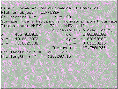
The top line of the analysis box contains the name of the file associated with the picked surface. The next two lines contain the name of the object and the N, M location of the nearest node point picked on the object. The type of surface is displayed next, followed by the NMAX, MMAX dimensions of the surface. Coordinate data and distance to the previously picked point are displayed next. Finally, the arc lengths of the N and M curves at the picked point are presented.
If the picked surface is non-rectangular, that is, all defining curves do not have the same number of points, the analysis box looks like this:
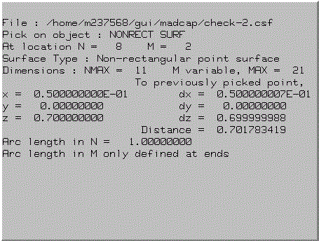
Most data is the same as on the rectangular surface, but note that since the value of M is variable, this is written out and only the largest value of M is reported. Also, since the arc length in M can only be computed at the extremes in N, no value for arc length in M can be presented.
If the picked object is a single curve, the M data is removed completely, as shown in the example below.
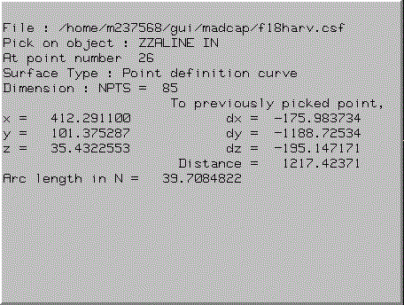
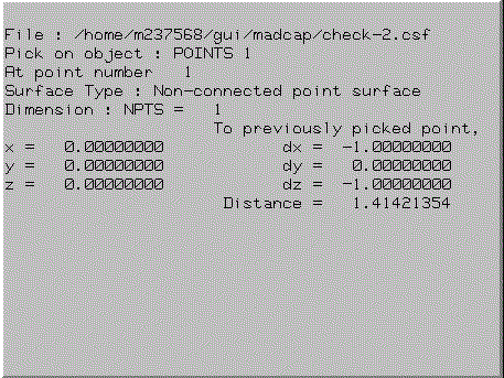
If the picked object is a non-connected point type surface, no arc length data is available, and the display is as shown below.
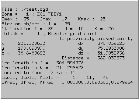
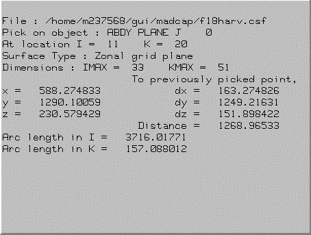
Finally, if the picked surface is two-dimensional and rectangular, but is a zonal plane, the N and M descriptors are replaced with one of I, J, or K, as defined for the grid plane. An example is shown below.
The middle mouse button is used in MADCAP to re-center the graphic image. If the middle mouse button is pressed and released, the image is re-centered to the selected point on the display, with no rescaling being performed. If the middle mouse button is pressed and held down, a zoom box is swept out with the picked point at its center. When the middle mouse button is released after sweeping out a zoom box, the image is recentered to the selected point and rescaled such that the image inside the zoom box becomes the full display in the main drawing area.
The right mouse button is used to respond to prompts from the program to select displayed objects such as points, curves, surfaces, and zones. Depending on the type of object being prompted for, the right mouse pick will extract a lower dimensional object from any higher dimensional object. If the prompt is for "Any" object, the full object definition is selected. The right mouse button may also be used to select a name from the name list if it is not displayed or hard to distinguish in the graphics display. If the prompt is for a point or curve and the user selects a two-dimensional surface name from the name list, the first point or curve in the surface definition will be selected. The right mouse button should also be used to select the on-screen buttons for aborting operations, signaling the end of multiple selection inputs, or selecting the contents of the object manager results buffer.
If the SHIFT key is held down while clicking the left mouse button over a displayed surface, the display of that surface is toggled off. Any surface whose display is toggled off in this way is saved in a reject buffer so that it can be quickly retrieved again by using the SHIFT-right mouse toggle on function.
Any surface whose display has been turned off by using the SHIFT-left mouse toggle off function can be quickly retrieved by simply clicking the right mouse button in the main display area while holding down the SHIFT key. This function can continue to be used to retrieve previously toggled-off surfaces to the depth of the toggle reject stack, currently set at 100 surfaces. Note that when toggling surfaces back on, the currently set display file will be changed to the file associated with the surface you are toggling back on. Likewise, in a .cgd file, the currently set zone will be changed to the zone associated with the toggled on surface if it is not the zone currently set to display from in the .cgd display list. Any surfaces that are associated with a file that has been closed since it was first toggled off are removed from the reject stack and unavailable for re-display with this function.
If the ALT key is held down while clicking the left mouse button over a displayed surface, the display of that surface is turned off. The surface will not be saved in the reject buffer and can not be redisplayed with the SHIFT-right mouse button.
Last updated 12 June 2007