
GMAN was then used in graphics mode to cut a hole in the airfoil grid around the flap, define the fringe boundaries for both grids, and set the remaining boundary conditions. The file demo.jou is the journal file created during the interactive GMAN session, with the addition of comments describing the procedure.
The first step, obviously, is to start GMAN.
   gman

                                ***** gman *****

             Select the desired version from the following list.

   0) END
   1) gman_pre optimized version

   Single program automatically selected.

    ****************************************************************************
    * Warning: This software contains technical data whose export is           *
    * restricted by the Arms Export Control Act (Title 22, U.S.C., Sec 2751,   *
    * et seq.) or Executive Order 12470. Violation of these export-control     *
    * laws is subject to severe criminal penalties. Dissemination of this      *
    * software is controlled under DoD Directive 5230.25 and AFI 61-204.       *
    ****************************************************************************
               GMANPRE - Version 6.163 (last changed 2007/02/14 16:35:41)
                           Creating journal file 'gman.jou'.
     Enter SWITCH or GRAPHICS to change to graphics mode.
    GMAN:
At this point, you could type @demo.jou to execute the commands stored in the journal file demo.jou. You could also enter commands individually at the GMAN: prompt. Or, you could enter SWITCH or GRAPHICS to enter graphics mode.
The following sections describe in detail the use of GMAN for the airfoil/flap configuration. The graphics mode steps are on the left, with the Main Menu steps left-aligned and the Menu Options indented. Most of these are accomplished in GMAN by clicking on the listed menu item using the left mouse button. A few require entering text in the prompt area at the bottom of the screen. (See the "Graphical User Interface Basics" section of the GMAN User's Guide for a description of the various sections of the GMAN screen layout.)
The command line equivalents are shown on the right. Note that, in general, several graphics mode steps become consolidated into a single command. A few of the commands are too long to fit on a single line, and are thus shown with the continued part indented. When using GMAN in command-line mode, however, they should be entered on a single line.
We first need to tell GMAN the name of the file containing the grid.
| Graphics Mode | Command Line Mode |
|---|---|
|
Common File enter demo.cgd | FILE demo.cgd |
Next, we need to cut a hole in the airfoil grid surrounding the flap.
The first step is to select the zone containing the airfoil grid, and to select the "Overlapping" boundary type. (This boundary type is useful for setting boundary conditions on interior grid points, as well as for Chimera grids.)
| Graphics Mode | Command Line Mode |
|---|---|
|
BOUNDARY COND. 1: (from Zone List) OLAP |
ZONE 1 BOUNDARY OLAP |
We need to tell GMAN the procedure we're going to use to define the hole. In this case the hole will be defined by grid surfaces that form a closed region around the flap.
| Graphics Mode | Command Line Mode |
|---|---|
|
MODIFY BNDY SHOW OTHER ZONE 2: (from Zone List) PICK K-PLANE * OLAP GENERATION GENERATE HOLES SET/SHO CUTTER CUTTER SURFACE | CUTTER SURFACE TYPE |
Next, we select the surfaces from the flap grid that specify a closed region around the flap defining the hole.
The j = 1 surface in the flap grid (i.e., the flap surface itself) could be used. However, the flap grid is tightly packed near the flap surface to resolve the boundary layer, while the airfoil grid spacing in this region is much larger. Ideally, the exchange of information between the two grids should occur in regions where the grid cells are similar in size.
Using a grid line farther out, near the outer edge of the flap zone, would result in a hole bigger than the flap grid. Since the boundary conditions around the hole for the solution in the airfoil zone will be computed from the solution in the flap zone, this would be unacceptable.
For these reasons, the j = 26 grid line around the flap is used.
| Graphics Mode | Command Line Mode |
|---|---|
|
SET SRF ZON enter 2 SET SURF RANGE enter 20 26 1 enter 160 26 1 |
CUTTER SURFACE IN ZONE 2 I20 J26 K1 TO I160 J26 K1 INCREMENT 1 |
|
SET SURF RANGE enter 20 1 1 enter 20 26 1 |
CUTTER SURFACE IN ZONE 2 I20 J1 K1 TO I20 J26 K1 INCREMENT 1 |
|
SET SURF RANGE enter 160 1 1 enter 160 26 1 |
CUTTER SURFACE IN ZONE 2 I160 J1 K1 TO I160 J26 K1 INCREMENT 1 |
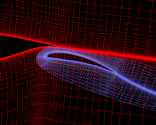
The surfaces defining the hole cutter are shown by the yellow lines in the figure below, along with both grids in the region of the flap.

All overlapping boundaries and holes must have a unique label, greater than six. The Label menu choice is in the Subregion Selection area in the lower-right corner of the GMAN window.
| Graphics Mode | Command Line Mode |
|---|---|
|
Label enter 7 | LABEL 7 |
Finally, we can create the hole.
| Graphics Mode | Command Line Mode |
|---|---|
| GENERATE HOLE | GENERATE HOLE |
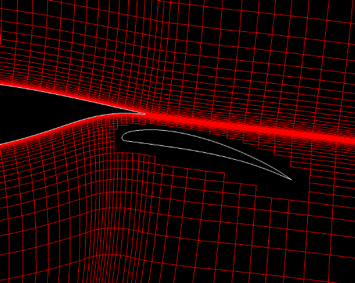
The resulting airfoil grid, with the hole cut into it, is shown below in the region of the flap.

The next step is to define the fringes and set boundary conditions on them. For the airfoil grid, the fringes will be defined as the hole boundary.
| Graphics Mode | Command Line Mode |
|---|---|
|
OLAP GENERATION GENERATE FRINGE FRG MODE HOLE | FRINGE-MODE HOLE |
|
GENERATE FRINGE * OLAP GENERATION | GENERATE FRINGE |
|
SET FRINGE BND COUPLE 2: (from Zone List) OLAP COUPLE |
SET FRINGE BOUNDARY COUPLED TO ZONE 2 BOUNDARY OLAP |
|
BOUNDARY COND. YES, SAVE CHANGES | UPDATE |
The flap grid is completely embedded in the airfoil grid, and the outer boundaries do not overlap any solid boundaries. Cutting a hole is thus not necessary, and we can use the outer boundaries as the fringe.
| Graphics Mode | Command Line Mode |
|---|---|
|
PICK ZONE/BNDY 2: (from Zone List) OLAP |
ZONE 2 BOUNDARY OLAP |
|
MODIFY BNDY GENERATE FRINGE FRG MODE OUTER BOUND I1 ON BOUND IMAX ON BOUND JMAX ON |
FRINGE-MODE OUTER BOUNDARY ON I1 FRINGE-MODE OUTER BOUNDARY ON IMAX FRINGE-MODE OUTER BOUNDARY ON JMAX |
|
Label enter 8 | LABEL 8 |
|
GENERATE FRINGE * OLAP GENERATION | GENERATE FRINGE |
|
SET FRINGE BND COUPLE 1: (from Zone List) OLAP COUPLE |
SET FRINGE BOUNDARY COUPLED TO ZONE 1 BOUNDARY OLAP |
|
BOUNDARY COND. YES, SAVE CHANGES | UPDATE |
The remaining boundary conditions that need to be set for the C grid around the airfoil are the downstream outflow boundaries, the outer boundary, the C grid cut line, and the airfoil surface. The downstream and outer boundaries of the flap grid have already been coupled to the airfoil grid, so all that remain are the C grid cut line and the flap surface.
The downstream outflow boundaries for the airfoil grid are at I1 and IMAX, and are defined as outflow boundaries.
| Graphics Mode | Command Line Mode |
|---|---|
|
PICK ZONE/BNDY 1: (from Zone List) I1 |
ZONE 1 BOUNDARY I1 |
|
MODIFY BNDY CHANGE ALL OUTFLOW | OUTFLOW |
|
BOUNDARY COND. YES - UPDATE FILE | UPDATE |
|
PICK ZONE/BNDY IMAX | BOUNDARY IMAX |
|
MODIFY BNDY CHANGE ALL OUTFLOW | OUTFLOW |
|
BOUNDARY COND. YES - UPDATE FILE | UPDATE |
The outer boundary of the airfoil grid is at JMAX, and is defined as a freestream boundary.
| Graphics Mode | Command Line Mode |
|---|---|
|
PICK ZONE/BNDY JMAX | BOUNDARY JMAX |
|
MODIFY BNDY CHANGE ALL FREESTREAM | FREESTREAM |
|
BOUNDARY COND. YES - UPDATE FILE | UPDATE |
The C grid cut line and the airfoil surface are both at J1. First, we'll couple the grid to itself, using "point match" coupling. This will define the cut line as a coupled boundary, leaving the points on the airfoil surface undefined.
| Graphics Mode | Command Line Mode |
|---|---|
|
PICK ZONE/BNDY J1 | BOUNDARY J1 |
|
MODIFY BNDY COUPLE 1: (from Zone List) SET COUP MODE POINT MTCH ON SEL OTHER BNDY J1: COUPLE |
CPMODE POINT MATCH COUPLED TO ZONE 1 BOUNDARY J1 |
Now, we'll set a viscous wall condition at the remaining undefined points, and write the changes to the .cgd file.
| Graphics Mode | Command Line Mode |
|---|---|
|
CHANGE BY TYPE UNDEFINED VISCOUS WALL | UNDEFINED IS VISCOUS WALL |
|
BOUNDARY COND. YES - UPDATE FILE | UPDATE |
Like the airfoil grid, the cut line and the flap surface in the flap grid are both at J1. The boundary conditions there are set in the same way as in the airfoil grid.
| Graphics Mode | Command Line Mode |
|---|---|
|
PICK ZONE/BNDY 2: (from Zone List) J1 |
ZONE 2 BOUNDARY J1 |
|
MODIFY BNDY COUPLE 2: (from Zone List) SEL OTHER BNDY J1: COUPLE | COUPLED TO ZONE 2 BOUNDARY J1 |
|
CHANGE BY TYPE UNDEFINED VISCOUS WALL | UNDEFINED IS VISCOUS WALL |
|
BOUNDARY COND. YES - UPDATE FILE | UPDATE |
Finally, it's a good idea to check the boundary conditions to make sure all is OK. [This checks regular (non-fringe) boundaries. Fringe boundaries can also be checked, using RUN FRNG CHKS in graphics mode, or CHECK FRINGE in command line mode. Doing the fringe boundary check for this case yields several messages about volume ratios exceeding the tolerance. This is intended as a warning about differences in the sizes of the grid cells in the two zones in the area of the fringes. As noted earlier, the grid cells in this area should be similar in size. For this case, however, this does not seem to present a problem in the solution.]
| Graphics Mode | Command Line Mode |
|---|---|
| TOP | |
| CHECK | ZONE ALL |
|
CHECK BOUNDARY PICK ZONE ALL (from Zone List) RUN BNDY CHKS | CHECK BOUNDARY |
After hitting the Enter key to return to graphics mode, we can quit GMAN.
| Graphics Mode | Command Line Mode |
|---|---|
|
END YES - TERMINATE | EXIT |
Last updated 29 Apr 2008