
This document describes the use of Wind-US to solve a problem using a Chimera, or overset, grid. It is primarily intended to demonstrate the use of GMAN for Chimera grids. [The various files discussed in this document may be downloaded from the Wind-US documentation WWW site, as discussed in the Downloading Files section.]
The geometry is a 2-D airfoil with a flap, shown below.

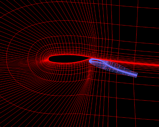
Separate C grids have been created for the airfoil and the flap, with the flap grid overlaying the airfoil grid, as shown below.

The outer boundary of the airfoil grid actually extends far beyond the airfoil, but is expanded in the figure to show the details near the surface. The two grids are contained in a multi-zone formatted PLOT3D xyz file. The airfoil grid is zone 1, with 205 × 59 points, and the flap grid is zone 2, with 179 × 33 points. In the figure, every other point in both directions, for both grids, has been omitted.
In the sections that follow:
Last updated 16 Mar 1999