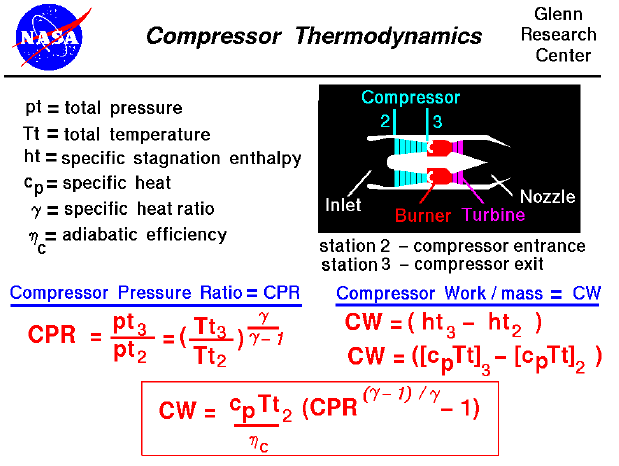

A text only version of this slide is available which gives all of the flow equations. The interactive Java applet EngineSim is also available. This program solves these equations and displays the thrust and fuel flow values for a variety of turbine engines.
Most modern passenger and military aircraft are powered by gas turbine engines, also called jet engines. All types of jet engines have some parts in common. All jet engines have a compressor to increase the pressure of the incoming air. There are currently two principal compressor designs found on jet engines: the axial compressor, in which the air flows parallel to the axis of rotation, and the centrifugal compressor, in which the air is turned perpendicular to the axis of rotation. In either design, the job of the compressor is to increase the pressure of the flow. We measure the increase by the compressor pressure ratio (CPR), which is the ratio of the air total pressure (pt) exiting the compressor to the air pressure entering the compressor. This number is always greater than 1.0. Referring to our station numbering, the compressor entrance is station "2" and the compressor exit (burner entrance) is station "3". The CPR is equal to pt3 divided by pt2, as shown on the slide.
To produce the increase in pressure, the compressor must perform work on the flow. In the axial compressor, cascades of small airfoils are mounted on a shaft that turns at a high rate of speed. Several rows, or stages, are usually used to produce a high CPR, with each stage producing a small pressure increase. In the centrifugal compressor, an additional pressure increase results from turning the flow radially (radiating from or converging to a common center). Since no external heat is being added to or extracted from the compressor during the pressure increase, the process is isentropic. The temperature ratio across the compressor is related to the pressure ratio by the isentropic flow equations.
Work must be done to turn the shaft on which the compressor is mounted. From the conservation of energy, the compressor work per mass of airflow (CW) is equal to the change in the specific enthalpy of the flow from the entrance to the exit of the compressor. (The term "specific" means per mass of airflow.) The enthalpy at the entrance and exit is related to the total temperature at those stations, as shown on the slide. Performing a little algebra, we arrive at the equation in the box at the bottom of the slide that relates the work required to turn the compressor to the compressor pressure ratio, the incoming total temperature, some properties of the gas (specific heats [cp] and heat ratios [gamma]), and an efficiency factor (nc). The efficiency factor is included to account for the actual performance of the compressor as opposed to the ideal, isentropic performance. In an ideal world, the value of the efficiency would be 1.0; in reality, it is always less than 1.0. So additional work is needed to overcome the inefficiency of the compressor to produce a desired CPR. The work is provided by the power turbine, which is connected to the compressor by the central shaft.
Notice that the CPR is also related to the total temperature ratio across the compressor. Since the CPR is always greater than 1.0 and the value of gamma (the ratio of specific heats) is about 1.4 for air, the total temperature ratio is also greater than 1.0. The air heats up as it passes through the compressor. There are material limits (http://www.ueet.nasa.gov/parts.htm) on the temperature of the compressor. On some engines, the temperature at the exit of the compressor becomes a design constraint (a factor limiting the engine performance). You can now use EngineSim to study the effects of different materials on engine operation.
Navigation..
Go to...
byTom
Benson
Please send suggestions/corrections to: benson@grc.nasa.gov