Return to Contents
Airfoil Panels
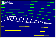
 The Airfoil View Panel provides a schematic drawing of the
airfoil
problem.
This schematic displays the airfoil shape and the
streamlines
of flow around the
airfoil. Flow moves from left to right.
The airfoil is colored white. The
green
streamlines flow
over the top of the foil and the
yellow pass below. The
white
lines indicate the
stagnation
streamlines which end on the airfoil surface.
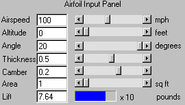
 The Airfoil Input Panel controls the shape and attitude of the
airfoil
displayed in Airfoil View Panel. You can vary all the
parameters which
affect the
lift of
an airfoil using the input boxes and sliders.
 |
- Airspeed - Speed of the
air in the simulated tunnel
- Altitude - Height of the tunnel above the mean sea level
- Angle - Angle of attack of the airfoil
- Thickness - Thickness
of the airfoil
- Camber - Curvature of the airfoil
- Wing
Area - Wing area
You can vary the display by using the
sliders on the Airfoil View Panel. Use In and
Out sliders to zoom the size. The position
can be changed with
the Left/Right and Up/Down sliders.
As
the angle,
thickness,
or camber
are varied, the
geometry
in the Airfoil View Panel is changed and the value of lift
is
computed and displayed in the output box and gauge at the
bottom. As the
airspeed
is increased, the lift will change.
Varying the
altitude
changes the local density and the lift generated by the
wing.
The units for the various parameters
are given to the right
of the sliders.
 The
Lift of an airfoil can have a very wide range of values.
To obtain the
value of the lift, take the number given in the
output box at the left and multiply by the number to the right
of the gauge.
The multiplier is always shown in powers of 10.
The
Lift of an airfoil can have a very wide range of values.
To obtain the
value of the lift, take the number given in the
output box at the left and multiply by the number to the right
of the gauge.
The multiplier is always shown in powers of 10.
For a given altitude, the current Density,
Pressure, and Temperature are shown at the bottom
of the Airfoil View
Panel.
Other Topics:
View a
General Description of FoilSim
Operation.
Use the
Plotter Control Panel to record the
variation of lift,
pressure,
and speed around the airfoil.
Explore the flowfield by
using the Probe Control.
Print and Save the data.
Please send any comments to:
Curator:
Tom.Benson@grc.nasa.gov
Responsible Official:
Kathy.Zona@grc.nasa.gov
 The Airfoil View Panel provides a schematic drawing of the
airfoil
problem.
This schematic displays the airfoil shape and the
streamlines
of flow around the
airfoil. Flow moves from left to right.
The airfoil is colored white. The
green
streamlines flow
over the top of the foil and the
yellow pass below. The
white
lines indicate the
stagnation
streamlines which end on the airfoil surface.
 The Airfoil Input Panel controls the shape and attitude of the
airfoil
displayed in Airfoil View Panel. You can vary all the
parameters which
affect the