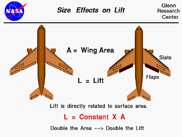

The amount of lift generated by an object depends on the size of the object. Lift is an aerodynamic force and therefore depends on the pressure variation of the air around the body as it moves through the air. The total aerodynamic force is equal to the pressure times the surface area around the body; lift is the component of this force perpendicular to the flight direction. Since most of the lift is generated by the wings, and lift is the force perpendicular to the flight direction, we find that lift is directly proportional to the wing planform area. The planform area is the area of the wing as viewed from above the the wing, looking along the "lift" direction. It is a flat plane, and is NOT the surface area (top and bottom) of the entire wing, although it is almost half that number for most wings. Increasing the wing area will increase the lift. Doubling the area will double the lift.
This slide shows the projected surface area for two different aircraft. The airplane on the left is shown in a cruise condition while the airplane on the right is shown in a takeoff or landing condition. Takeoff and landing are times of relatively low velocity, so to keep the lift high (to avoid the ground!) designers try to increase the wing area. This is done by sliding the flaps backwards along metal tracks and shifting the slats forward to increase the wing area. The next time you fly in an airliner, watch the wings during takeoff and landing to see the change in wing area.
Since aircraft come in many shapes and sizes, an aerodynamicist has to be able to compute the wing area for many different shapes. Most of these skills are learned in high school.
Let's investigate the dependence of lift on wing area by using a Java simulator.
You can vary the wing area by changing the wing span or the chord length by using the sliders below the view window or by backspacing over the input box, typing in your new value and hitting the Enter key on the keyboard. The wing area is the product of the span and the chord for the red rectangular wing shown in the view window. On the right is a graph of the lift versus wing area. The red dot shows your conditions. Below the graph is the numerical value of the lift and the computed wing area. You can display these values in either English or Metric units by using the choice button next to the lift output box. Click on the choice button and select from the drop-menu. There is an additional three dimensional effect on wing lift caused by the downwash from the wing tips. The amount of the effect depends on the Aspect Ratio of the wing, which is the span divided by the chord for a rectangular wing. You can see the magnitude of the effect by turning the correction ON and OFF, using the choice button to the right of the output box for Aspect Ratio.
As an experiment, set the chord to 5.0 feet and and the span to 50 ft. Note the amount of lift. Now increase the span to 100 ft. What is the new value of lift? How does this value compare to the previous value? Now set the span to 50 ft and the chord to 10 ft. What is the new value of lift? How does this value compare to the previous value?
You can further investigate the effect of wing size and the other factors affecting lift by using the FoilSim II Java Applet. You can also download your own copy of FoilSim to play with for free.
Navigation..
Go to...
byTom
Benson
Please send suggestions/corrections to: benson@grc.nasa.gov