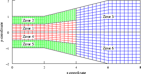
Three-zone mesh, input to cfbeta

cfbeta may be used to add zones to a common grid (.cgd) or common flow (.cfl) file that are symmetric to existing zones. For example, a grid or flowfield for a complete aircraft configuration may be created from an existing half-span grid or flowfield, for additional calculations at non-zero yaw angles.
Input to cfbeta is specified in a keyword input file, with the three-letter extension .inp. Lines in the input file starting with a "/" are comments. The following keywords and parameters may be specified.
| CHECK | Checks the input file for errors without performing any operations.
| |||
| FILE file_in | The input .cgd or .cfl file.
| |||
| OUTPUT file_out | The output common file, with the added symmetric zones.
If the file is a .cgd file, the
reflection
(i.e., symmetry) boundaries are converted to
coupled
boundaries, and coupling data is generated and included in the
output file.
Other boundary types in the newly-added zones will be the
same type as the corresponding boundaries in the original zones.
| |||
| BETA PLANE [X|Y|Z] value | ||||
| The location in physical space of the symmetry plane, which must
be a constant x, y, or z plane.
Warning - all the reflection (i.e., symmetry) boundaries in the original zones will be coupled to the corresponding boundaries in the newly-added zones. No check is made to verify that they lie on the specified symmetry plane. It may thus be necessary to make corrections using GMAN. | ||||
| SWITCH DIRECTION [I|J|K] IN ZONES nzone1 nzone2 | ||||
| This keyword specifies the index (for structured grids) or direction (for unstructured grids) that should be reversed in the newly-added zones, so that they have the same "handedness" as the grids in the original zones. For structured grids, I, J, and K correspond to the i, j, and k indices; for unstructured grids, they correspond to the x, y, and z directions. If nzone1 = 0, the specified index or direction will switch in all the newly added zones, and nzone2 need not be specified. Otherwise the specified index or direction will switch in zones nzone1 through nzone2. A choice must be specified for all the zones. | ||||
Note: Users have reported problems with this utility when the original grid contains bleed regions. It is therefore recommended that GMAN be used to delete the bleed regions in the original grid (i.e., redefine them as some other type of boundary, such as a viscous wall) before using cfbeta. Then, after using cfbeta, use GMAN to recreate the bleed regions at the desired locations in the new grid.
Example
Suppose we have the three-zone structured grid shown in the following figure, for the upper half of a simple two-dimensional diverging duct. The y = 0 plane is a symmetry plane, and the j = 1 boundaries in zones 1 and 3 are reflection boundaries.

A six-zone grid for the full duct may be created using the following input file for cfbeta, named cfbeta3.inp. Note that even though this is a two-dimensional configuration, it's still necessary to switch one of the index directions.
   / Input grid file
   /
   FILE testa.cgd
   /
   / Output grid file
   /
   OUTPUT testb.cgd
   /
   / Symmetry plane at y = 0.
   /
   BETA PLANE Y 0.0
   /
   / Switch k index direction in new zones
   /
   SWITCH DIRECTION K IN ZONES 0
The terminal session is shown below. Lines in a slanted font are typed by the user.
   % cfbeta

                                ***** cfbeta *****

             Select the desired version from the following list.

   0) END
   1) cfbeta

   Single program automatically selected.

   Omit the .inp extension!
   Enter cfbeta INPUT FILE ............. (<CR>=cfbeta.inp) : cfbeta3
    cfbeta - Version 1.8 (last changed 2007/02/13 22:16:01)
    ****************************************************************************
    * Warning: This software contains technical data whose export is           *
    * restricted by the Arms Export Control Act (Title 22, U.S.C., Sec 2751,   *
    * et seq.) or Executive Order 12470. Violation of these export-control     *
    * laws is subject to severe criminal penalties. Dissemination of this      *
    * software is controlled under DoD Directive 5230.25 and AFI 61-204.       *
    ****************************************************************************
     CREATING BETA GRID FROM ZONE   1
     CREATING BETA GRID FROM ZONE   2
     CREATING BETA GRID FROM ZONE   3
     CREATING BETA BOUNDARIES FOR ZONE   1
     CREATING BETA BOUNDARIES FOR ZONE   2
     CREATING BETA BOUNDARIES FOR ZONE   3
The resulting six-zone grid is shown below.

Last updated 20 July 2007