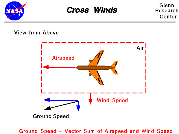

One of the most confusing concepts for young aerodynamicists is the relative velocity between objects. Aerodynamic forces are generated by an object moving through the air, but the air itself can also move. Aerodynamic forces depends on the square of the velocity between the object and the air. To properly define the velocity, it is necessary to pick a fixed reference point and measure velocities relative to the fixed point. In this slide, the reference point is fixed on the ground, but it could just as easily be fixed to the aircraft.
The air in which the aircraft flys can move in all three directions. In this figure, we are only considering velocities which occur perpendicular to the flight path but parallel to the ground. The effect of wind along the flight path has been considered in the previous slides. Updrafts and downdrafts which occur perpendicular to the ground are described in another slide. In this figure, we are viewing the aircraft from above and have assumed that the wind is blowing at a constant velocity from right to left as viewed from the cockpit.
The aircraft moves through the air at some velocity called the airspeed. The air moves at some constant velocity called the wind speed which is perpendicular to the airspeed. The chief effect of the cross wind will be to deflect the flight path in the direction of the wind. The aerodynamic lift force depends on the airspeed and is not related to a constant cross wind. The cross wind will simply add another vector component to the ground speed . This, in turn, will affect the flight trajectory.
(The description given for this slide concerns only static performance. This means that the wind is steady and the aircraft is aligned along it's flight path. Unsteady cross wind gusts will introduce additional forces on the aircraft due to changes in the angle of attack of the vertical stabilizer and, depending on the cross-sectional shape of the fuselage, some changes in lift. Additional forces can also be generated by yawing, or turning, the aircraft along the flight path by using the rudder. These effects are not discussed in this slide.)
Go to...
byTom
Benson
Please send suggestions/corrections to: benson@grc.nasa.gov