Aerodynamicists use
wind tunnels
to test
models
of proposed aircraft and engine components.
During a test, the model is placed in the
test section
of the tunnel and air is made to flow past the model.
Various types
of tests can be run in a wind tunnel.
Some tests are performed to directly measure the aerodynamic
forces and
moments
on the model.
The most basic type of instrument used in this type of testing is the
force balance.
We live in a world that is described by three, mutually perpendicular, spatial dimensions;
left to right, up and down, back and forth.
To completely describe the conditions on the aircaft model,
we must therefore measure the forces in each of three directions
and the moments, or rotations, about three directions.
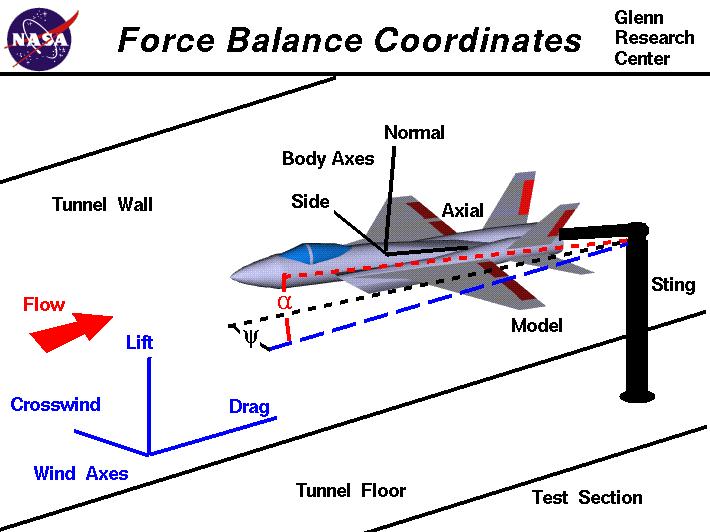
There are several different coordinate systems that can be used to describe three-dimensional
space. On the figure we show two such coordinate systems, the wind axes
which are aligned with walls of the wind tunnel, and the body axes which are
aligned to the geometry of the aircraft model. If the force balance is placed
inside
the model, it measures forces and moments along the body axes.
If the force balance is
external
to the model, it measures forces and moments along the wind axes.
The type of model
mount
employed can also limit the types of measurements that can be made and the
axes of the measurements.
Whether we use an internal balance or an external balance, we must eventually
resolve
the measured forces into
lift,
drag, and side force,
and the moments into
pitching moment,
rolling moment, and
yawing moment.
Drag and lift are defined to be the components of the
aerodynamic force
in the streamwise and perpendicular flow directions respectively.
So lift, drag and side force are directly measured in the wind axes. To bring the
measurements in the body axes into the wind axes requires some
trigonometry.
On the figure, the model is inclined to the wind axes by two angles. Alpha (the angle in red)
is the angle of attack, and psi (the angle in black) is the angle of yaw.
We can relate the measurements in the body axes to the wind axes by the following equations.
Let's let A = the measured axial force, N be the measured normal force,
S be the measured side force in the body axes. Similarly let AM be the moment
about the axial axis, NM be the moment about the normal axis, and SM be the
moment about the side aixs.
The lift L is given by:
L = N cos(alpha) - A sin(alpha)
The drag D is given by:
D = A cos(alpha) cos(psi) - N sin(alpha) cos(psi)
The crosswind force C is:
C = S cos(psi) + A cos(alpha) sin(psi) - N sin(alpha) sin(psi)
Converting the moments is a little more difficult than the forces because the moments are defined
about a certain point on the aircraft. With b as the
wing span and c as the mean aerodynamic chord, the
pitching moment PM is given by
PM = SM cos(psi) + (b/c)AM cos(alpha)sin(psi) + (b/c)NM sin(alpha) sin(psi)
Similarly, the yawing moment (YM) is equal to
YM = NM cos(alpha) - AM sin(alpha)
and the rolling moment (RM) is equal to
RM = AM cos(alpha)cos(psi) - (c/b)SM sin(psi) + NM sin(alpha)sin(psi)
Navigation ..

- Beginner's Guide Home Page
|