Aerodynamicists use
wind tunnels
to test
models
of proposed aircraft and engine components.
During a test, the model is placed in the
test section
of the tunnel and air is made to flow past the model.
Various types of instrumentation are used to determine the forces
on the model.
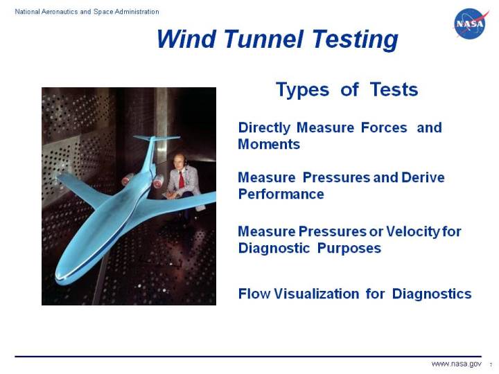
There are four main types of wind tunnel tests.
In some wind tunnel tests, the aerodynamic
forces and
moments
on the model are measured directly. The model is
mounted
in the tunnel on a special machine called a
force balance.
The output from the balance is a signal that is related
to the forces and moments on the model.
Balances can be used to measure both the
lift and
drag forces.
The balance must be calibrated against
a known value of the force before, and sometimes during, the test. Force measurements usually
require some data reduction or post-test processing to account for
Reynolds number
or
Mach number
effects on the model during testing.
It is very important in data reports to always specify the
reference value
of variables used in data reduction.
In some wind tunnel tests, the model is instrumented with pressure taps
and the component
performance
is calculated from the pressure data.
Total pressure
measurement is the normal procedure for
determining aircraft
inlet performance.
Theoretically, the
aerodynamic force
on an aircraft model could be obtained using pressure instrumentation
by integrating the pressure times an incremental area around the entire surface of the model.
But, in practice, pressure integration
is not used because of the large number of taps necessary to accurately resolve
pressure variations.
Airfoil drag
can be determined by integrating the total pressure deficit in the wake created
by a wing model.
In some wind tunnel tests, the model is instrumented to provide
diagnostic information
about the flow of air around the model. Diagnostic instrumentation includes
static pressure taps,
total pressure rakes,
laser Doppler velocimetry, and
hot-wire velocity probes.
A diagnostic test does not provide overall aircraft performance, but helps the
engineer to better understand how the fluid moves around and through the model. There are
a variety of flow control devices that are employed to improve
performance of the aircraft, if the local flow conditions are known.
Depending on the type of instrumentation used in the experiment,
steady state flow or unsteady, time-varying, flow information can be obtained.
The engineer must use some experience when employing flow
diagnostic instrumentation to properly place the instruments in regions of flow gradients
or separations.
In some wind tunnel tests,
flow visualization
techniques are used to
provide diagnostic information. Visualizaation techniques include free stream smoke,
laser sheet, or surface oil flow. The assumption is made that the flow visualization
medium moves exactly with the flow. Shadowgraphs or schlierin systems are used
to visualize the shape and location of shock waves in compressible flows. For low speed
flows, tufts or surface oil indicate the flow direction along the surface of a model.
You can investigate some wind tunnel testing techniques by using our
interactive tunnel testing applet.
More experienced users can use the
TunnelSys application programs to perform model
design, testing, and performance post-processing.
Navigation ..


- Beginner's Guide Home Page
|