Aerodynamicists use
wind tunnels
to test models of proposed aircraft.
In the tunnel, the engineer can carefully control the
flow conditions which affect
forces
on the aircraft. By making careful measurements of the forces on
the model, the engineer can predict the forces on the full scale
aircraft. And by using special diagnostic techniques, the engineer
can better understand and improve the performance of the aircraft.
Wind tunnels are designed for a specific purpose and
speed range.
There is a wide variety of
wind tunnel types
and model instrumentation.
The tunnel shown in the figure is a low-speed,
closed tunnel
which we are viewing from above.
We can use this figure to study the various parts of a wind tunnel.
The air inside the tunnel is made to move by the
fan
on the far side of the tunnel.
In this figure, air moves counter-clockwise around the circuit.
The fan is turned by a large, electrically-powered
drive motor.
Leaving the fan, the air is turned in the corners by turning vanes.
The turning vanes are a cascade of airfoils which minimize the
total pressure loss through the corners.
Leaving the corner at the upper left of the figure, the air passes through
some flow straighteners before entering the test section.
The purpose of the flow straighteners is to make the flow in the
test section as uniform as possible.
The test section is the part of the wind tunnel in which the
model is placed.
For low speed tunnel
operation, the test section has the smallest
cross-sectional area
and the highest velocity within the tunnel.
Leaving the test section, the air enters the
diffuser where it is expanded and slowed before returning to the
fan. Again, the diffuser is employed to minimize losses in the tunnel.
For this closed circuit wind tunnel, there are two more corners with turning vanes
before the air is brought back to the fan.
A similar arrangement of parts is found in the
open return
wind tunnel, except for the turning vanes.
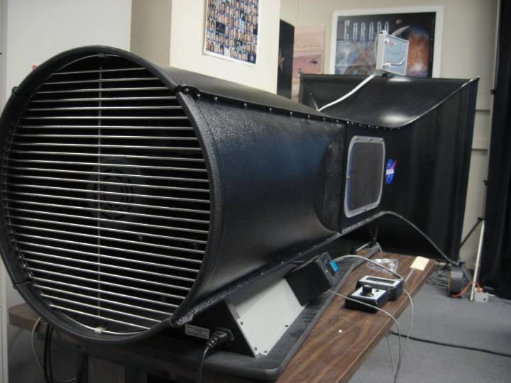
Here is a picture of an open return tunnel that is currently being used by the NASA Glenn Research
Center's Educational Program's Office. This wind tunnel is a commercially available Pitsco AirTech tunnel
and, because its size and speed is similar to the
Wright 1901 wind tunnel,
has been designated as the NASA Glenn Wright Memorial Tunnel (WMT).
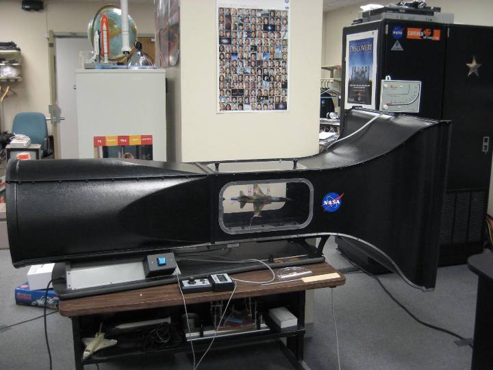
Airflow through this tunnel is from right to left. The largest part,
at the right of the tunnel, is called the bellmouth. For this tunnel, the
flow straighteners are placed at the entrance to the bellmouth as shown here.
The flow is constricted and the flow speed is
increased
through the bellmouth. The flow then enters the test section
shown in this photo.
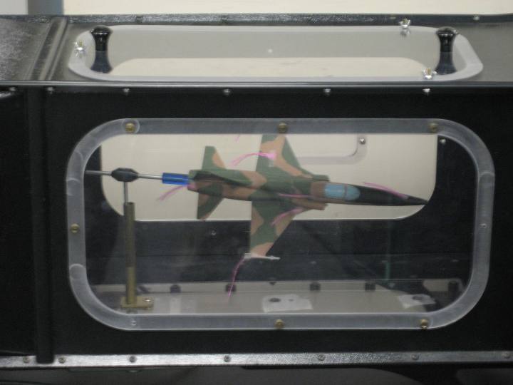
A tufted model of an F-5 fighter plane is shown in the test section.
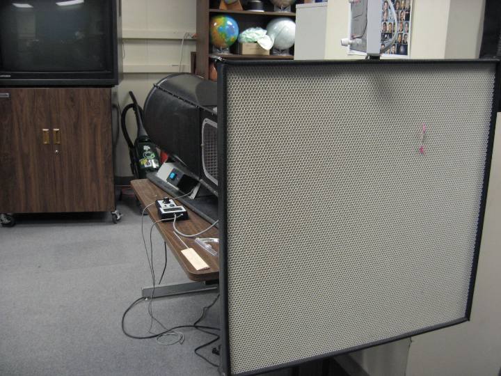
Air is drawn over the model by a fan located at the far left of the tunnel. In this photo,
one can see the motor that drives the fan, an exit screen to protect the user, and the diffuser
from the test section to the tunnel exit.
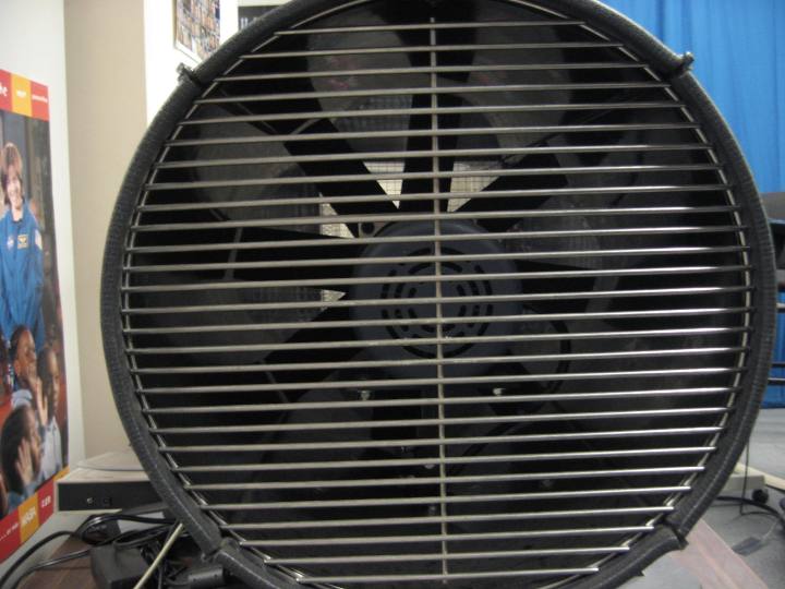
More details of the fan can be seen in this photo taken directly behind the tunnel. The flow
exits the wind tunnel into the room where it is re-circulated back into the bellmouth. To insure
flow uniformity in the test section, the tunnel bellmouth and exit must be located at some
distance from objects in the room.
Navigation ..


- Beginner's Guide Home Page
|