
|
Types of Wind Tunnels
|
Glenn
Research
Center
|
Aerodynamicists use
wind tunnels
to test models of proposed aircraft.
In the tunnel, the engineer can carefully control the
flow conditions which affect
forces
on the aircraft. By making careful measurements of the forces on
the model, the engineer can predict the forces on the full scale
aircraft. And by using special diagnostic techniques, the engineer
can better understand and improve the performance of the aircraft.
Wind tunnels are designed for a specific purpose and speed range.
Therefore, there are many different types of wind tunnels and several
different ways to classify wind tunnels. In this section of the website we shall
present various types of wind tunnels and discuss some of the unique features
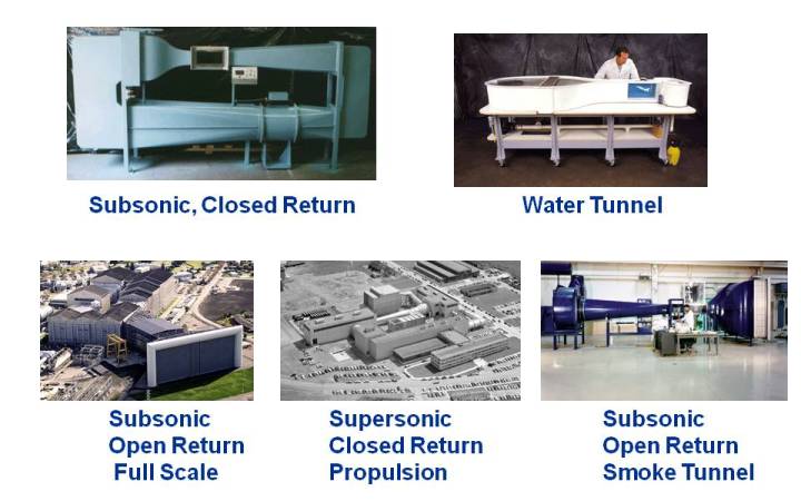
of each type of tunnel. On the figure, we show several examples
of wind tunnels and their designation.
Let us consider the various ways that
we classify wind tunnels. Details for the various types of wind tunnels are provided
on separate web pages.
Speed Regime
Wind tunnels are often denoted by the speed in the test section relative to the
speed of sound.
The ratio of the air speed to the speed of sound is called the
Mach number.
Tunnels are classified as
subsonic (M < .8) ,
transonic (.8 < M < 1.2) ,
supersonic (1.2 < M < 5.0) , or
hypersonic (M > 5.0).
The distinction by Mach number is caused by the realtive importance of
compressibility efffects.
For subsonic flows, we may neglect the effects of compressibility; for transonic
and supersonic flows, compressibility effects must be considered. For hypersonic
flows, we must make additional considerations for the chemical state of the gas. The
scaling effects of the Mach number can be theoretically
derived from the
conservation of momentum of the air in the tunnel.
Compressibility affects the
design of the test section
of a wind tunnel: for subsonic tunnels, the
test section
has the smallest cross-sectional area of the tunnel; for supersonic tunnels,
the throat of the nozzle has the smallest area and the test section area is chosen to
achieve
a desired Mach number in the test section.
Tunnel Geometry
Wind tunnels are also designated by the geometry of the tunnel.
A wind tunnel that is open on both ends and draws air from the room into
the test section is called an
open return
tunnel. The tunnel at the lower
right of the figure is an open return tunnel.
A wind tunnel that is closed and re-circulates the air through the
test section is called a
closed return
tunnel. The tunnel in the upper left of
the figure is a closed return tunnel. A
blowdown
wind tunnel has a high pressure vessel upstream of the test
section and a low pressure resevoir downstream of the test section. Blowdown
tunnels are used for supersonic testing. For hypersonic testing, a variation of the blowdown
tunnel called a shock tube is often used. Test times in a blowdown tunnel or shock tube
are much less than in a continuous flow tunnel.
NASA wind tunnels are often designated by the cross-sectional dimensions of the test section.
The wind tunnel in the lower center of the figure is the NASA Glenn 10 x 10. whose test section
is 10 foot high and 10 foot across. At the lower left is the NASA Ames 80 x 120, which is a full scale,
low speed wind tunnel.
Working Fluid
Wind tunnels can be designated by the type of fluid that is used in the tunnel. For most low
speed aircraft wind tunnel testing,
air is moved through the tunnel. To visualize shock waves for high speed
aircraft, or to study the flow around submarines or boats, water is used as the working fluid.
A water tunnel is shown at the upper right of the figure. In some hypersonic facilities, nitrogen or
helium has been used as the working fluid. Similarly, cryogenic nitrogen has been used for high
Reynold's number testing of transonic flows.
There are several wind tunnels around the world that are used to study ice build-up on aircraft parts.
These icing tunnels include refigeration devices to cool the air in the tunnel and water spray
devices to provide liquid droplets in the test section.
Special Purpose
Wind tunnels are often designated by the special pupose for which they were designed and built.
Propulsion wind tunnels have special requirements for handling the high temperature exhaust
from turbine or rocket engines. Flow Visualization or "smoke" tunnels must also handle the
exhaust contaminants that are used in the tunnel. Wind tunnels that are used to study the stability
of aircraft must allow the model to move freely within the test section. Certain high temperature
facilities have been designed to more accurately simulate the high temperature
effects of hypersonic flows.
Navigation ..


- Beginner's Guide Home Page
|