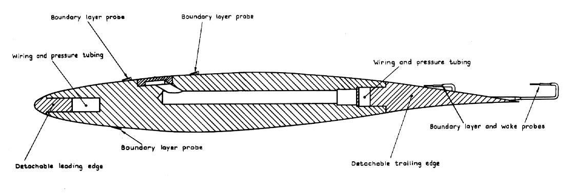
Figure 1. RAE 2822 transonic airfoil (From Ref. 1).
Figure 1. RAE 2822
transonic airfoil (From Ref. 1).
This validation case examines the transonic flow over the RAE 2822 airfoil as reported from reference 1. This case correponds to test case 6. Table 1 indicates the freestream flow conditions of that case.
| Mach | Reynolds Number | Angle-of-Attack (deg) |
|---|---|---|
| 0.725 | 6.5 million | 2.92 |
The geometry consists of the RAE 2822 airfoil. The coordinates of the lower and upper surfaces of the airfoil, as reproduced from Table 6.1 of (Cook et al., 1979), can be found in the file geom.txt. The coordinates are normalized according to the chord. The Fortran 90 program geom.f90 is a simple program which creates data files (yl.pts,yu.pts) for the ICEM CFD grid generator.
The computational domain for this case is bounded by a no-slip airfoil surface and a farfield boundary placed a significant distance from the airfoil.
This case corresponds to Case 6 from Ref. 1. Comparison data consists of pressure coefficients and boundary layers profiles obtained from experiments conducted at RAE and reported in 1979 in Ref. 1.
| Study | Category | Person | Comments |
|---|---|---|---|
| Study #1 | Example | J.W. Slater | Demonstrates computation of airfoil flows |
| Study #2 | Verification | J.W. Slater | Mach 0.3 inviscid flow at 0 angle-of-attack for zero drag |
| Study #3 | Example | J.W. Slater | Demonstrates application of overset grids |
| Study #4 | Validation | J.W. Slater | Compares WIND 5.0 to experimental data |
| Study #5 | Validation | C. Nelson | Explores turbulence model variations |
1. Cook, P.H., M.A. McDonald, M.C.P. Firmin, "Aerofoil RAE 2822 - Pressure Distributions, and Boundary Layer and Wake Measurements," Experimental Data Base for Computer Program Assessment, AGARD Report AR 138, 1979.