Aerodynamicists use
wind tunnels
to test models of proposed
aircraft and aircraft components. The model is placed in the
test section
of the tunnel
and air is made to flow past the model.
In some wind tunnel tests, the
aerodynamic forces
on the model are measured.
In some wind tunnel tests, the model is instrumented to provide diagnostic
information about the flow of air around the model. Model instrumentation
can include
static pressure taps,
tufts on the surface, or
total pressure rakes.
Some wind tunnel models are designed to determine the performance of a
particular component of the aircraft.
The aircraft
inlet and
nozzle
bring airflow into and out of the
gas turbine
propulsion system.
The performance of the inlet and nozzle depend on both the flight conditions of the aircraft
and the operation of the turbine engine. Special wind tunnel models are used
to determine the performance of the inlet and the
nozzle.
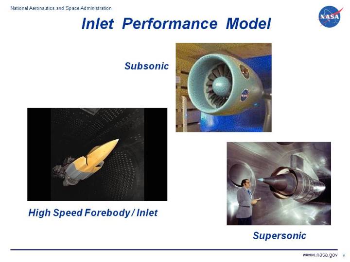
On this page we show several examples of inlet performance wind tunnel models.
The model at the lower left is a forebody/inlet model mounted in the NASA Glenn 8x6 foot
transonic tunnel. The model at the upper center is a subsonic inlet model mounted in the
NASA Glenn 9x15 foot subsonic tunnel.
The model at the lower right is a supersonic inlet model mounted
in the NASA Glenn 10x10 foot supersonic tunnel.
There are several unique features to inlet wind tunnel models and testing.
Inlet performance
is characterized by three factors:
-
Total pressure recovery is the ratio of the average
total pressure
at the exit of the inlet to the free stream total pressure. A higher
pressure recovery indicates a better performing inlet. The maximum
possible value of recovery is 1.0.
-
Compressor face distortion characterizes the variation of pressure across the
exit of the inlet. There are many different distortion factors used in the
aerospace industry. The simplest factor takes the maximum measured total pressure
minus the minimum measured total pressure divided by the average total pressure. More
sophisticated models use mass or area weighted averages. Inlet distortion is an
important factor because highly distorted flows cause
compressor stalls
that can damage the engine or disrupt flow through the engine.
-
Inlet spillage drag is a drag that occurs when the engine cannot handle all of the flow
that approaches the inlet. The airflow through the engine is set by choked conditions in
the nozzle. Any excess flow that approaches the inlet is spilled around the inlet generating
additional drag on the airframe.
The airflow through an inlet model is varied during a test to determine the effects of
engine airflow on both spillage drag and recovery. Engine airflow is varied by using a
calibrated plug at the exit of the inlet.
The flow going into the inlet is influenced by any object upstream of the inlet.
Therefore, an inlet model
often include a model of the forebody of the aircraft.
The flow is also affected by the angle of attack and angle of yaw of the aircraft.
Inlet models must often be pivoted during
a test to determine the effects of maneuvers on inlet operation.
For supersonic inlets,
shock waves
are generated by the airframe and inlet surfaces.
Boundary layers
generated on the surfaces can interact with the shock waves to create separated
regions in the inlet that decrease recovery and increase distortion. Flow control
devices used in the inlet, such as boundary layer bleed, must be properly modeled
in the wind tunnel test.
Inlet testing usually contains a combination of flow visualization,
diagnostic instrumentation,
and performance instrumentation. The chief performance instrumentation for
an inlet test is the
40 probe rake.
The rake is used to both
determine the inlet pressure recovery and the inlet distortion parameter values.
Navigation ..


- Beginner's Guide Home Page
|