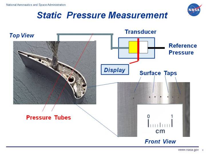
This page shows two photographs of a wind tunnel model of a
turbine blade.
The model is used for diagnostic testing to determine the
pressure distribution around the blade.
At the lower right of the figure, we have labeled the pressure taps which
are small holes drilled perpendicular to the surface of the blade.
Because the flow around the blade is tangent to the surface, the taps are
also perpendicular to the local flow direction and are pressurized by the random
component of the air velocity. The pressure in the taps is the static pressure as
discussed in
Bernoulli's equation.
To measure the pressure, long thin tubes connect the taps to a pressure transducer
located outside of the wind tunnel model. In this figure, the transducer is shown
in a schematic drawing.
The transducer measures the difference in pressure between the pressure in the tube
and a reference pressure. A typical transducer measures the strain in a thin element using
an electronic
strain gauge
as shown in red on the drawing.
The reference pressure is arbitrary, but should be noted in any data report. Possible reference
pressures include the external free stream static value, the wind tunnel total pressure, or a static
value located somewhere on the model.
Either an average, steady state pressure, or a time-varying, unsteady pressure value can be obtained
depending on the capabilities of the transducer.
Looking at the picture of the model, on the left, we see that diagnostic models are
complex, precise, and normally quite expensive pieces of equipment. The model must be
carefully
designed
to place the pressure taps where they can provide the most
information
to the engineer.
Routing pressure taps to the transducer is obviously a challenging engineering and
manufacturing problem.
Navigation ..


- Beginner's Guide Home Page
|