Aerodynamicists use
wind tunnels
to test
models
of proposed aircraft and engine components.
During a test, the model is placed in the
test section
of the tunnel and air is made to flow past the model.
Various types
of tests can be conducted in a wind tunnel.
Force balances.
are used to directly measure the aerodynamic
forces and
moments
on the model.
We must measure three forces (lift, drag, and side) and three moments
(pitch, roll, and yaw) to determine all of the
forces and moments
on the model.
There are several different methods for mounting
the model inside the test section.
The choice of mounting system in a
particular wind tunnel is often driven by the
type of balance being employed.
For an
external balance,
measuring devices are located outside of the model and the tunnel.
For an external balance, the mount must transmit the aerodynamic loads on the
model to the external balance, and hold the model securely at the desired
flight condition of angle of attack and angle of yaw.
For an
internal balance,
the measuring devices are located inside the model.
The mount does not have to transmit forces, but must provide a
path for information to be passed from the model to
data recording devices. Bundles of tubes for
pressure measurements,
or wires from
strain gages must then be passed
through the mount to the
control room.
The choice of balance type and the type of mount can also affect the
data reduction
for the model.
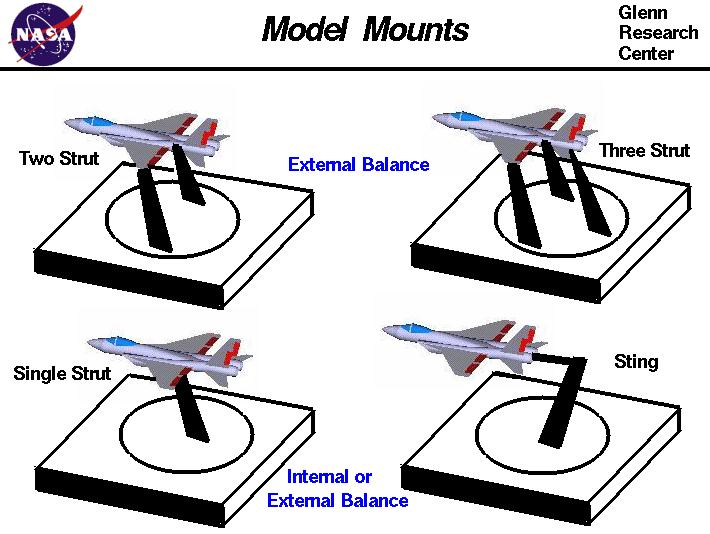
On the figure, we show four different methods for mounting a
fighter aircraft model in a tunnel and we shall discuss the
advantages and disadvantages for each method.
For all of the mounting systems, the struts are normally sheilded from the air in the tunnnel so that
the drag of the struts themselves is not included in the drag of the aircraft.
At the upper right, we have a three strut mount that connects to the model near
both wing tips and at the aft end. The three strut mount is used most often with external
balances; the bottom of the three struts connect to a platform that is instrumented with
strain gages. With three movable struts, the
angle of attack
and
roll angle
can be accurately set and sustained while
yaw
is provided by turning the model on the circular section of the platform.
The disadvantage of this system is the expense, complexity and maintenance for three movable struts.
Aerodynamic interference between the struts and the model and flow blockage in
the tunnel are also concerns for a three strut mount. Less expense, interference, and
blockage can be obtained by the two strut mount at the upper left. But the two strut
mount is less rigid than the three strut in pitch and roll. Even less expensive and with
a minimum of interference and blockage is the single strut mounting system shown at the bottom.
The single strut can be attached to the top or bottom of the model as shown at the left bottom, or it can
be attached to the rear of the model, as a sting mount, as shown at the right bottom. The sting
mount has less interference with the model flow field than the one strut mount, but the aft end of the
model may be distorted to accept the sting mount.
Single strut mounts are less rigid than multiple strut mounts. The single strut mount works very
well with internal balances and flow diagnostics.
Navigation ..


- Beginner's Guide Home Page
|