Aerodynamicists use
wind tunnels
to test
models
of proposed aircraft and engine components.
During a test, the model is placed in the
test section
of the tunnel and air is made to flow past the model.
Various types
of instrumentation are used to determine the forces on the model.
The most basic type of instrument is the force balance.
Force balances are used to directly measure the aerodynamic
forces and
moments on the model.
On this page, we will discuss a simplified measurement of the
lift force
to demonstrate the basic principles involved with force balances.
This configuration is called a one component balance since it
only measures one force.
There are more sophisticated,
three-component balances that can measure
lift,
drag and
pitching moment.
A six-component balance is required to
measure all three forces (lift, drag, and side) and three moments
(pitch,
roll, and
yaw)
that determine an aircraft's motion through the air.
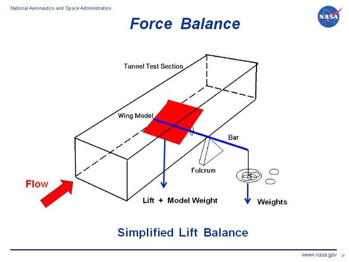
As shown in the figure, a wing model is
mounted
in the tunnel on a bar that passes through the side of the tunnel. The bar passes over a fulcrum and
the force generated by the model is
balanced
by weights placed on a plate hung from the end of the bar.
With the tunnel turned off and no air passing
through the test section, weights are added to the plate to balance the weight of the model.
The tunnel is then turned on and air flows over the model. The model generates an aerodynamic lift force.
In the figure, the leading edge of the wing model is lower than the trailing edge. In this case, the
wing will generate a lift force that is in the same direction as the weight of the model (downforce).
The bar is no longer in balance; the end outside the tunnel is higher than the previous setting.
Additional weights are added to the plate to re-balance the bar. The amount of the added weight is
equal to the magnitude of the aerodynamic lift of the model.
If the model had been mounted with a positive
angle of attack, one would have to remove weights from the plate to bring the bar back into balance.
This very simplified mechanical method of determining lift can be used with a
student-built
wind tunnel.
Some student wind tunnels are equipped with electronic instrumentation to
determine drag.
To accurately determine the aerodynamic forces and moments on an aircraft model in a "real"
wind tunnel requires much more sophisticated instrumentation. Electronic
strain gages
are placed
inside
the model, or on a measuring
platform
outside the tunnel. Multiple gages permit the determination of multiple forces during the same test.
Navigation ..


- Beginner's Guide Home Page
|