Aerodynamicists use
wind tunnels
to test
models
of proposed aircraft and engine components.
During a test, the model is placed in the
test section
of the tunnel and air is made to flow past the model.
Various types
of tests can be run in a wind tunnel.
Some tests are performed to directly measure the aerodynamic
forces and
moments
on the model.
The most basic type of instrument used in this type of testing is the
force balance.
We must measure six components, three forces (lift, drag, and side) and three moments
(pitch, roll, and yaw), to completely describe the conditions on the model.
For some tests, only
three components (lift, drag, and pitch)
are measured.
In some wind tunnels, the measuring devices are located external to the
model and the test section. In other tunnels, the measuring devices are placed
inside
the model. The location of the device affects the choice of
mounting system
for the model and the
data reduction
necessary to determine the aerodynamic forces.
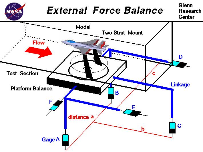
On this web page we will examine the external balance.
As shown in the figure, an idealized fighter plane model is attached to a platform located beneath
the test section by a two strut mount.
There are six
strain gages,
labeled A through F, that are connected to the platform.
Each gage measures a force by the stretching of an electrical element in the gage.
The stretching changes the resistance of the element which changes the
measured current through the element according to
Ohm's law.
The model can be rotated in
pitch and
roll
by its connections to the struts, and rotated in
yaw by the circular section in the floor of the test section.
A test is conducted in the following manner.
With the tunnel turned off and no air passing
through the test section, the
weight (W)
of the model and mounting system is determined as the sum of the forces from
gages A, B, and C.
The tunnel is then turned on and air flows over the model. The model generates aerodynamic forces
and moments that changes the readings on the strain gages.
The
lift (L)
is given by:
L = A + B + C - W
The
drag (Dr) is given by:
Dr = E + D
The side force Y is:
Y = F
If there is no
rolling moment, the values of A and B are equal. If there is a rolling moment
(RM), the value is equal to:
RM = (A - B) * a / 2
Similarly, the
yawing moment, (YM) is equal to
YM = (D - E) * c / 2
and the
pitching moment, (PM) is equal to
PM = C * b
Notice that the gages are aligned with or perpendicular to the walls of the wind tunnel. The reduction
of the data from the gages gives forces and moments that are
aligned
with the wind tunnel walls.
An assumption is made that the flow in the tunnel is perfectly aligned with the walls.
Navigation ..


- Beginner's Guide Home Page
|