
Flying model rockets is a relatively safe and inexpensive way for students to learn the basics of aerodynamic forces and the response of vehicles to external forces. Like an airplane, a model rocket is subjected to the forces of weight, thrust, and aerodynamics during its flight. The weight and aerodynamics are determined by the design of the model rocket components. The thrust is provided by a replaceable solid rocket engine which can be purchased at local hobby or toy stores.
Model rocket performance (how far, how high, how fast) depends a great deal on the rocket engine performance. But there are several different ways to characterize rocket engine performance. Model rocket engines come in a variety of sizes, a variety of weights, with different amounts of propellant, with different burn patterns which effects the thrust profile, and with different values of the delay charge which sets the amount of time for the coasting phase of the flight. On this page, we discuss all of the engine performance factors that affect the flight of a model rocket.
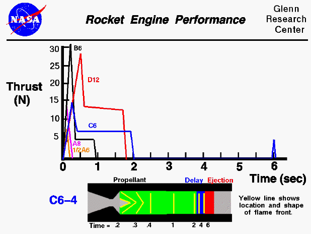
At the top of the page we show typical performance curves for several different rocket engines. We are plotting the thrust of the engine versus the time following ignition for each engine. You will notice that when comparing engines, there is a great difference between the levels and shapes of the plots. And for any single engine, the thrust changes from time to time. At the bottom of the page, we show a typical engine schematic which we will use to explain why the thrust changes so much for a given engine. The thrust of any engine depends on how fast and how much hot gas exhaust passes through the nozzle. Solid rocket fuel only burns on the surface and the surface burns away as it turns into a gas. You can then imagine the flaming surface moving with time through the propellant. The flaming surface is called the flame front. At any time and at any location the amount of hot gas being produced depends on the area of the flame front. The greater the area, the greater the thrust. As the propellant burns away the shape and the area can change.
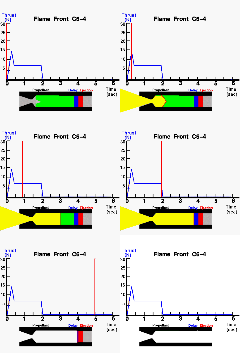
Here is a computer animation of the movement of the flame front for a typical engine
In the animation, we show the shape and location of the flame front for a C6-4 engine. (We will explain the engine designations later on this page). The schematic is two dimensional while the real engine is three dimensional. So a three dimensional cone surface will appear as a two dimensional angle on the schematic. The flame front is shown as a red line and it moves through the propellant as the engine burns. The hot exhaust is shown in yellow. The time is noted on the plot by a moving red line. On a typical model rocket engine, a small cone is formed in the propellant on the nozzle end of the engine. As the fuel burns, the size of the cone increases until it hits the engine casing (about time = .2 on this engine). Between time = .2 and .5, the shape of the cone flattens out and the area and thrust decreases because the burn rate also depends on the curvature of the surface. By time = .5, the cone has become a flat flame front which proceeds on down the engine until the propellant is used up at time = 2. Between .5 and 2, the thrust is constant; at time = 2 the thrust goes to zero and the delay charge begins to burn. Even though the delay charge is shorter (smaller) than the propellant, it burns longer because it is made of a different material. For this engine we have a 4 second delay (the "4" of C6-4 denotes the delay time) . At time = 6 the ejection charge is reached and ignited and blows out the front of the engine.. NOTE:This animation is not time accurate. The fuel burning is shown every .1 seconds, while the delay charge is displayed every .5 seconds. In reality, the fuel burn is very fast and the delay burn relatively long.
Considering the various engine plots, we see a burn pattern similar to the previously discussed C6-4, but with some variations in the amount of thrust. We have seen that the shape of the thrust curve is affected by the shape of the flame front. Designers of solid rockets can produce the given thrust curves by changing the total amount of propellant placed in the engine, by varying the the angle of the cone in the propellant, and by varying the diameter of the propellant (and casing). Considering a single engine plot, the thrust varies greatly with time. We can specify a time-averaged thrust of the engine by adding up the product of the thrust over some small time increment times the amount of the time increment and then dividing by the total time. The number designation of an engine indicates the average thrust in Newtons. A C6-4 has an average thrust of 6 Newtons. The average thrust times the length of the engine burn in time is called the total impulse of the engine. The letter designation of an engine tells the maximum total impulse of that class of engine. An "A" engine has a maximum impulse of 2.5 Newton-seconds, a "1/2A" has 1.25 N-sec, a "B" has 5.0 N-sec, a "C" has 10.0 N-sec, and a "D" has 20.0 N-sec. If we compare the curves for B6 and the C6, we find that both engines have the same average thrust (6 Newtons), but the "C" engine burns almost twice as long for double the total impulse.
As mentioned above, the engine designer can affect the thrust and the total impulse of an engine by changing the diameter of the propellant (and casing). Typical "1/2A" engines are 13 mm in diameter, typical "A", "B" and "C" engines are 18 mm in diameter, and typical "D" engines are 24 mm in diameter. This is important to remember because a model rocket designed for a "B" engine will not accept a "1/2A" or a "D". The engines will not fit into the fixed engine mount of the rocket.
Go to...
byTom
Benson
Please send suggestions/corrections to: benson@grc.nasa.gov