NASA Glenn Videoconference:
Rocket Science
Post-Conference Activity: Bottle Rockets and Propulsion
(If so instructed by your teacher, print out a worksheet
page.)
Objective:
During the completion of this activity, you will demonstrate science processing
skills, an ability to use technological design, and an ability to identify factors
that affect motion and forces.
Background Information:
Bottle rockets are excellent devices for investigating Newton's Three Laws
of Motion:
1st Law - A rocket will remain on the launch pad until an unbalanced
force is exerted, propelling the rocket upward.
2nd Law - The amount of force depends upon how much air is pumped
inside the rocket. You can increase the force further by adding a small amount
of water, which increases the mass the rocket expels by the air pressure.
3rd Law - Finally, the action force of the air (and water) as
it rushes out the nozzle creates an equal and opposite reaction force propelling
the rocket upward.
As with a balloon, air pressurizes the bottle rocket. Adding a small amount
of water to the bottle increases the action force. The water expels from the
bottle before the air does, turning the bottle rocket into a bigger version
of a water rocket toy (available in toy stores).
In order to learn more about model rockets and how they work, follow these
links to information on Flight
of a Model Rocket, Parts
of a Model Rocket, and Forces
on a Model Rocket.
Instructions:
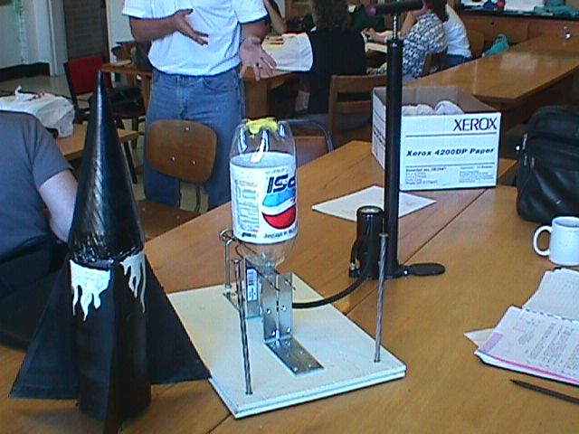
- You will work in teams to construct a soda bottle rocket with an empty 2-liter
soda bottle. You and your team members must decide on the materials you will
use for the body, fins, and cone of the rocket (which is then placed over
the empty 2-liter soda bottle to be launched). You will then predict how well
your rocket will fly and record your prediction on the worksheet.
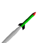
You may want to customize your rockets by decorating them in some way. An
example is shown below:
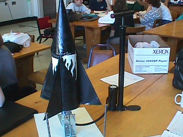
- One bottle rocket launcher (which can be constructed according
to the instructions shown below or bought from a science supply catalog) is
needed for the class. While one team launches their rocket, another team can
assist them by tracking the rocket, determining how high it flew, and recording
the information on a worksheet.
(Follow this link to learn how to measure the altitude reached by your rockets:
Model Rockets,
Measured Altitude.) You will then compare your prediction with the rocket's
actual performance and compare the flight of your rocket with other rockets.
Your final assignment will be a journal entry giving details on your design,
the comparisons you made, and your conclusions on the reasons for the rockets'
performances.
-
It is important to follow safety rules when launching bottle
rockets. Countdowns help everybody to know when the rocket will lift off.
Using the launch safety instructions shown below, develop specific launch
safety rules through group discussions. In the rules, include how far back
observers should stand, how many people should prepare the rocket for launch,
and who should retrieve the rocket.
Launch Safety Instructions:
- Select a grassy field that measures approximately 30 meters in width. Place
the launcher in the center of the field and anchor it in place with the spikes
or tent stakes. (If it is a windy day, place the launcher closer to the side
of the field from which the wind is blowing so that the rocket will drift
onto the field as it descends.)
- As you set up your rocket on the launch pad, observers should stand back
several meters. It is recommended that you rope off the launch site.
- The team member responsible for pumping air into the rocket should wear
eye protection. The bottle rocket should be pumped no higher than about 50
pounds of pressure per square inch.
- When pressurization is complete, everyone should stand in back of the rope
for the countdown.
- Continue to countdown and launch the rocket only when the recovery range
is clear.
- A team member should retrieve the rocket.
Instructions for Building the Launcher:
The launcher is simple and inexpensive to construct. Most needed parts are
available from hardware stores. In addition you will need a tire valve from
an auto parts store and a rubber bottle stopper from a school science experiment.
The most difficult task is to drill a 3/8-inch hole in the mending plate. An
electric drill is a common household tool. If you do not have access to a drill
or do not wish to drill the holes in the metal mending plate, find someone who
can do the job for you. Ask a teacher or student in your school's industrial
arts shop or the parent of a student to help.
Materials Needed
· 4 5-inch corner irons with 12 3/4-inch wood screws to fit
· 1 5-inch mounting plate
· 2 6-inch spikes
· 2 10-inch spikes or metal tent stakes
· 2 5-inch by 1/4-inch carriage bolts with 6 1/4-inch nuts
· 1 3-inch eyebolt with 2 nuts and washers
· 4 3/4-inch diameter washers to fit bolts
· 1 #3 rubber stopper with a single hole
· 1 Snap-in Tubeless Tire valve (small 0.453 inch hole, 2 inches long)
· Wood board 12 x 18 x 3/4 inches
· 1 2-liter plastic bottle
· Electric drill and bits including a 3/8-inch bit
· Screw driver
· Pliers or open-end wrench to fit nuts
· Vice
· 12 feet of 1/4-inch cord
· Pencil
Construction of the Launcher
- Prepare the rubber stopper by enlarging the hole with a drill. Grip the
stopper lightly with a vice and gently enlarge the hole with a 3/8 inch bit
and electric drill. The rubber will stretch during cutting, making the finished
hole somewhat less than 3/8 inches.
- Remove the stopper from the vice and push the needle valve end of the tire
stem through the stopper from the narrow end to the wide end.
- Prepare the mounting plate by drilling a 1-3/8 inch hole through the center
of the plate. (As safety precautions, hold the plate with a vice during
drilling and wear eye protection.) Using a drill bit slightly larger
than the holes, enlarge the holes at the opposite ends of the plates. The
holes must be large enough to pass the carriage bolts through them.
- Lay the mending plate in the center of the wood base and mark the centers
of the two outside holes that you enlarged. Drill holes through the wood big
enough to pass the carriage bolts through.
- Push and twist the tire stem into the hole you drilled in the center of
the mounting plate. The fat end of the stopper should rest on the plate.
- Insert the carriage bolts through the wood base from the bottom up. Place
a hex nut over each bolt and tighten the nut so that the bolt head pulls into
the wood.
- Screw a second nut over each bolt and spin it about halfway down the bolt.
Place a washer over each nut and slip the mounting plate over the two bolts.
- Press the neck of a 2-liter plastic bottle over the stopper. You will be
using the bottle's wide-neck lip for measuring in the next step.
- Set up two corner irons so that they look like bookends. Insert a spike
through the top hole of each iron. Slide the irons near the bottleneck so
that the spike rests immediately above the wide neck lip. The spike will hold
the bottle in place while you pump up the rocket. If the bottle is too low,
adjust the nuts beneath the mounting plate on both sides to raise it.
- Set up the other two corner irons as you did in the previous step. Place
them on the opposite side of the bottle. When you have the irons aligned so
that the spikes rest above and hold the bottle lip, mark the centers of the
holes on the wood base. (For more precise screwing, drill small pilot holes
for each screw and then screw the corner irons tightly to the base.)
- Install an eyebolt to the edge of the opposite holes for the hold-down
spikes. Drill a hole and hold the bolt in place with washers and nuts on top
and bottom.
- Attach the launch "pull cord" to the head end of each spike.
Run the cord through the eyebolt.
- Make final adjustments to the launcher by attaching the pump to the tire
stem and pumping up the bottle. Refer to the launching instructions for safety
notes. If the air seeps out around the stopper, the stopper is too loose.
Use a pair of pliers or a wrench to raise each side of the mounting plate
in turn to press the stopper with slightly more force to the bottleneck. When
satisfied with the position, thread the remaining hex nuts over the mounting
plate and tighten them to hold the plate in position.
- Drill two holes through the wood base along one side. The holes should
be large enough to accommodate large spikes (metal tent stakes). When the
launch pad is set up on a grassy field, the stakes will hold the launcher
in place as you yank the pull cord to launch the rocket.
- The launcher is now complete.
Rubrics:
Use the rubrics shown below as a guide when completing the activity.
Rubric for constructing the bottle rocket and recording
observations
(30 points max.)
| |
Yes
|
No
|
| Team carries out assignment criteria |
3 points |
0 points |
| Team performs testing safely |
1 point |
0 points |
| Records observations and findings are correct |
3 points |
0 points |
| Team demonstrates proper science process skills |
3 points |
0 points |
| Participates in class discussions |
5 points |
0 points |
| Team kept on task |
5 points |
0 points |
|
Bottle rockets fins aligned properly
|
3 points |
0 points |
|
Nose cone straight on rocket
|
3 points |
0 points |
|
Team contributes ideas to the class
|
4 points |
0 points |
Rubric for journal writing (Worksheet Question 6)
(12 points max.)
| |
Yes
|
No
|
| Carries out assignment criteria |
3 points |
0 points |
| Records observations and findings are correct |
3 points |
0 points |
| Demonstrates proper science process skills |
3 points |
0 points |
| Spelling, grammar, and punctuation correct |
3 points |
0 points |
Alternative Recommended Assessments:
- Evaluate each bottle rocket on its quality of construction. Observe how
well the fins align and attach to the bottle. Also observe the alignment of
the nose cone at the top of the rocket.
- Evaluate the design and quality of construction of each bottle rocket by
measuring and comparing the altitudes that the rockets reached.
Continue to the post-conference assessment.
Please send any comments to:
Web site related: Curator
Content related: Tom Benson (benson@nasa.gov)