Electrical circuits are used throughout aerospace engineering,
from flight control systems, to cockpit instrumentation, to engine
control systems, to
wind tunnel
instrumentation and operation.
The most basic circuit involves a single resistor
and a source of electric potential or voltage. Electrons flow through
the circuit producing a current of electricity. The resistance,
voltage, and current are related to one another by
Ohm's law.
There is usually more than one resistor used in a practical circuit.
In the analysis of circuits with
multiple resistors, we must determine if the resistors are subject to the
some voltage or to the same current. Multiple resistors in a
parallel circuit
are subjected to the same voltage. Multiple resistors in a
series circuit
are subjected to the same current. On this page we discuss an
the Wheatstone bridge circuit which is an
important circuit that is used in wind tunnel instrumentation
If we denote resistance by R, current by i, and voltage by
V, then Ohm's law states that for each resistor in the circuit:
V = i R
i = V / R
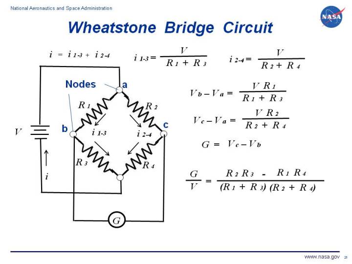
On the figure, we show a circuit consisting of a power source and four resistors
connected in a square. The resistors are connected to each other at nodes
which are labeled a through c. The circuit contains a potentiometer, labeled
G, which detects the voltage difference between nodes c and b.
The value from the potentiometer is displayed in the
control room.
If we consider each resistor separately, each resistor has its own current
(i1, i2, i3, and i4),
resistance
(R1, R2, R3 , and R4),
and voltage
(V1, V2, V3, and V4), which are related to each
other through Ohm's law.
In practice, the resistors would actually be the resistance provided by a
strain gage in a wind tunnel
force balance system.
Resistors R1 and R3 are connected in
series through node b. Therefore the
same current flows through R1 and R3.
i(1-3) = i1 = i3
and the value of i(1-3) can be determined from Ohm's law:
i(1-3) = V / (R1 + R3)
Similarly, resistors R2 and R4 are connected in series and the
same current i(2-4) flows through these resistors. The current is given by:
i(2-4) = V / (R2 + R4)
The change in voltage from nodes a to node b is given by:
Vb - Va = i(1-3) R1 = V R1 / (R1 + R3)
Similarly, the voltage change from node a to node c is given by:
Vc - Va = i(2-4) R2 = V R2 / (R2 + R4)
The potentiometer G measures the difference in voltage between nodes b
and c.
G = Vc - Vb = (Vc - Va)- (Vb - Va)
G = V [ {R2 / (R2 + R4)} - {R1 / (R1 + R3)} ]
G / V = [(R2 R3) - (R1 R4)] / [(R1 + R3) (R2 + R4)]
This final equation explains how a Wheatstone bridge circuit can be used to
eliminate temperature bias when using a strain gage to determine forces on a wind
tunnel model. Two strain gages are connected to the model, and the output from the
gages are put into a Wheatstone bridge as R1 and R2. Equal "ballast" resistors are
placed in R3 and R4. If the gage is subjected to an
increase in temperature, the resistance in both R1 and R2 increase by the same amount.
But because the potentiometer measures the difference in resistance between R1 and R2,
the reading stays the same.
Navigation ..

- Beginner's Guide Home Page
|