Electrical circuits are used throughout aerospace engineering,
from flight control systems, to cockpit instrumentation, to engine
control systems, to
wind tunnel
instrumentation and operation.
The most basic circuit involves a single resistor
and a source of electric potential or voltage. Electrons flow through
the circuit producing a current of electricity. The resistance,
voltage, and current are related to one another by
Ohm's law.
There is usually more than one resistor used in a practical circuit.
When analyzing a complex circuit, we can often group components together and
develop an equivalent circuit. In the analysis of circuits with
multiple resistors, we must determine if the resistors are subject to the
some voltage or to the same current. Multiple resistors in a
parallel circuit
are subjected to the same voltage. Multiple resistors in a
series circuit
are subjected to the same current. On this page we discuss the equivalent circuit
for resistors in series.
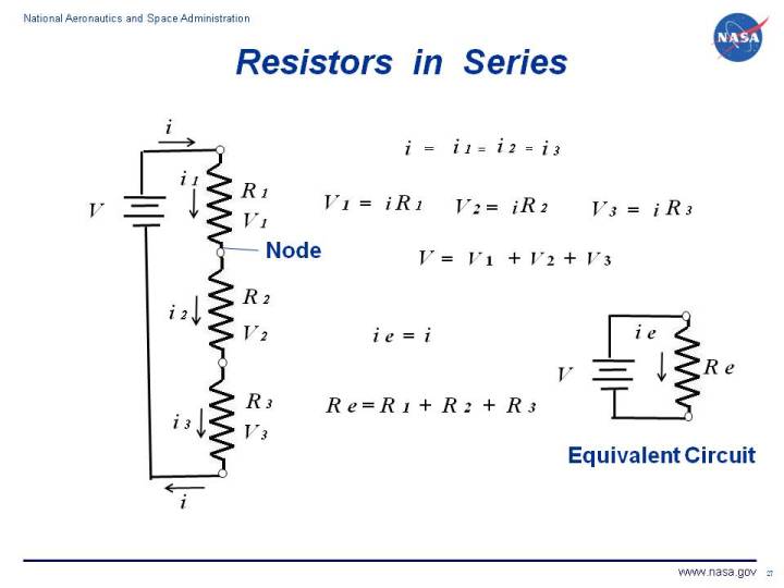
On the figure, we show a circuit consisting of a power source and three resistors
connected in series.
If we denote resistance by R, current by i, and voltage by
V, then Ohm's law states that for each resistor in the circuit:
V = i R
i = V / R
If we consider each resistor separtely, each resistor has its own current
(i1, i2, and i3),
resistance
(R1, R2, and R3),
and voltage
(V1, V2, and V3).
The resistors are connected to each other at nodes. The nodes are denoted by
small circles on the figure. For this circuit, there
are four nodes connecting the three resistors and the power source.
At each node, the current coming into the node
must equal the current leaving the node according to Faraday's Law.
For this arrangement of resistors, there is only one wire coming into and leaving
each node. Therefore, the current through each resistor must be the same.
i = i1 = i2 = i3
The voltage drop across each resistor is determined by Ohms law:
V1 = i R1
V2 = i R2
V3 = i R3
The sum of the voltage drops across each resistor must equal the voltage supplied
by the power source:
V = V1 + V2 + V3
We now know the voltage, resistance, and current through every part of the circuit.
If we were to construct an equivalent circuit as shown at the lower right, we would
have the same voltage V, the same current from the power source ie = i,
and a single equivalent resistor Re. For our equivalent circuit, Ohm's law
specifies that:
V = i Re
We can determine the value of Re by using the relations developed above and
a little algebra:
i Re = i R1 + i R2 + i R3
Re = R1 + R2 + R3
We can use this knowledge of the series resistor circuit to analyze the
Wheatstone bridge
circuit that is used for temperature control for wind tunnel
force balances
using electronic
strain gages.
Navigation ..

- Beginner's Guide Home Page
|