Aerodynamicists use
wind tunnels
to test
models
of proposed aircraft and engine components.
During a test, the model is placed in the
test section
of the tunnel and air is made to flow past the model.
Various types
of tests can be run in a wind tunnel.
Some tests are performed to directly measure the aerodynamic
forces and
moments
on the model.
The most basic type of instrument used in this type of testing is the
force balance.
We must measure
six components,
three forces (lift, drag, and side) and three moments
(pitch, roll, and yaw), to completely describe the conditions on the model.
But for some tests, only three components (lift, drag and pitch) are measured.
In some wind tunnels, the measuring devices are located
external
to the model and the test section. In other tunnels, the measuring devices are placed
inside
the model. The location of the device affects the choice of
mounting system
for the model and the
data reduction
necessary to determine the aerodynamic forces.
On this web page we will examine the internal balance.
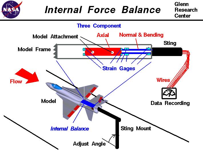
As shown in the lower left of the figure, an idealized fighter plane model is attached to
a sting and placed in the test section of a wind tunnel. At the top of the
figure we show the details of the model attachment to the sting. The model is
actually attached to a three-component balance system and the balance system is
attached to the sting. The three-component balance can detect the
axial and perpendicular, or normal, forces and the
bending along an axis perpendicular to the axial and normal axes.
From these measurements one can derive
the
lift ,
drag , and
pitch of the model, but cannot determine
the side force,
roll, or
yaw.
Forces on the model are detected by
strain gages
located on the balance.
Each gage measures a force by the stretching of an electrical element in the gage.
The stretching changes the resistance of the gage which changes the measured
current through the gage according to
Ohm's law.
Wires carry electricity to the gages through the hollow
sting and carry the resulting signal back through the sting to recording devices
in the
control room.
Multiple strain gages are arranged on the balance to account for temperature
changes on the model during the test. A
Wheatstone bridge
electrical circuit is used to provide temperature compensation.
Because this example uses only a three-component balance, the model must be aligned
with the flow in the tunnel to eliminate the side force, roll, and yawing moments.
We can only vary the angle of attack of the model, as shown at the left bottom of the figure.
With an internal balance, the forces are measured in a co-ordinate system attached
to the model. The resulting measurments must be
corrected
to produce the lift, drag, and pitching moment in the tunnel co-ordinate system.
When using a sting with an internal balance, the aft geometry of the
model
is often modified to accept the sting. Additional tests may be required to determine
the final aircraft drag with the true aircraft geometry.
Navigation ..


- Beginner's Guide Home Page
|