To move a hypersonic cruising aircraft through the air,
we have to use some kind of propulsion system
to generate thrust.
Because of the
heat
generated at stagnation points in a hypersonic flow, the
gas turbine
engine is not suited for this regime.
A better choice for an air-breathing propulsion system
would be a
ramjet
for
Mach numbers
less than 6, and a
scramjet
for Mach numbers greater than 6.
Ramjets and scramjets rely on the forward speed of
the vehicle to compress the air in the
inlet
instead of using the mechanical
compressor
of a gas turbine.
The
combustion section
of a ramjet is similar to the gas turbine, but the
ramjet needs no
power turbine since there is no compressor.
The
thermodynamics
of of a ramjet/scramjet and a turbine engine are quite similar.
To understand how a ramjet works, we must
study the basic thermodynamics of
gases.
Gases have various
properties that we can observe with our
senses, including the gas
pressure p,
temperature T,
mass, and
volume V
that contains the gas.
Careful, scientific observation has determined that these
variables
are related to one another, and the values of these
properties determine the
state
of the gas.
A thermodynamic process, such as
heating or
compressing the gas,
changes the values of the state variables in a
manner which is described by the
laws of thermodynamics. The
work done by a gas
and the
heat transferred to a gas
depend on the beginning and ending states of the gas and
on the process used to change the state.
It is possible to perform a series of processes, in which the state
is changed during each process, but the gas eventually
returns to its original state. Such a series of processes is
called a
cycle
and forms the basis for understanding engine operation.
On this page we discuss
the Brayton Thermodynamic Cycle which is used in
ramjets and scramjets.
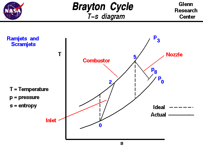
The figure shows a
T-s diagram
of the Brayton cycle. Using the turbine engine
station numbering system,
we begin with
free stream conditions at station 0.
In cruising flight, the
inlet slows the air stream
to compress it to station 2 conditions.
As the flow slows, some of the energy associated with the
aircraft velocity
increases
the static pressure
of the air and the flow is compressed. Ideally, the compression is
isentropic and the static
temperature is also increased as shown
by the dashed lines on the plot.
For an ideal, isentropic compression a vertical line on the
T-s diagram describes the process. In reality, the compression is not
isentropic and the compression process line leans to the right because
of the increase in
entropy of the flow.
The non-isentropic effects are the result of
shock waves
in the inlet. For the ramjet, there is a terminal
normal shock
in the inlet that brings the flow to subsonic conditions at the
burner. As speed increases, the losses through this shock eventually
decrease the level of pressure that can be achieved in the burner,
and this sets a limit on the use of ramjets. For supersonic combustion
ramjets (scramjets) there is no normal shock and the inlet shock losses
associated with the normal shock are avoided.
The
combustion process in the
burner occurs at constant pressure from
station 3 to station 5.
The temperature increase depends on the type of fuel used and the
fuel-air ratio.
For scramjets, there may be additional entropy losses associated
with the mixing of the fuel and the air.
Following combustion, the hot exhaust is then passed through the
nozzle.
Ideally, the nozzle
brings
the flow isentropically back to free stream pressure from
station 5 to station 8.
Since ramjets and scramjets often use converging-diverging nozzle
designs, there is often a mismatch between the
external flow pressure and the free stream.
The area under the T-s diagram is proportional to the useful work and
thrust
generated by the engine.
Activities:
Guided Tours
Navigation..


- Beginner's Guide Home Page
|
