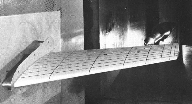
Figure 1. The ONERA M6 wing (Fig. B1-2 from reference 1.).
Figure 1. The ONERA M6 wing (Fig. B1-2 from reference 1.).
This case involves the flow over the ONERA M6 wing. It was tested in a wind tunnel at transonic Mach numbers (0.7, 0.84, 0.88, 0.92) and various angles-of-attack up to 6 degrees. The Reynolds numbers were about 12 million based on the mean aerodynamic chord. The wind tunnel tests are documented by Schmitt and Charpin in the AGARD Report AR-138 published in 1979 (Reference 1).
Some pages of the report by Schmitt and Charpin (mostly geometry information) are available as PDF files. The following pages have been scanned, Page: 1, 2, 3, 4, 5 & 6, 7, 20, 38.
The Onera M6 wing is a classic CFD validation case for external flows because of its simple geometry combined with complexities of transonic flow (i.e. local supersonic flow, shocks, and turbulent boundary layers separation). It has almost become a standard for CFD codes because of its inclusion as a validation case in numerous CFD papers over the years. In the proceedings of a single conference, the 14th AIAA CFD Conference (1999), the Onera M6 wing was included in 10 of the approximately 130 papers! Some of the papers using the ONERA M6 wing are listed as references below (Contact me if you wish to have your paper referenced).
Currently, the CFD simulations use the flow field conditions of Test 2308 of Reference 1. Table 1 lists these flow conditions. These correspond to a Reynolds number of 11.72 million based on the mean aerodynamic chord of 0.64607 meters.
| Mach | Reynolds Number | Angle-of-Attack (deg) | Angle-of-Sideslip (deg) |
|---|---|---|---|
| 0.8395 | 11.72E+06 | 3.06 | 0.0 |
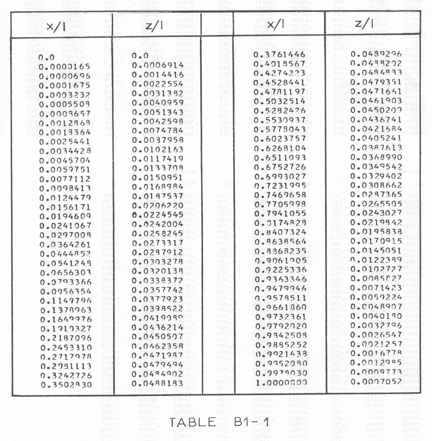
The ONERA M6 wing is a swept, semi-span wing with no twist. It uses a symmetric airfoil using the ONERA D section. The coordinates of the airfoil section at the (y/b) = 0.0 plane are listed on Page 7 and also in a picture of [Table B1-1] (Download Accessible PDF Plug-in) of the Schmitt and Charpin report. The file airfoil.txt is an ASCII text file containing these coordinates. The coordinates indicate that there is a finite thickness to the trailing edge. For CFD simulations, an approximation is usually made of a zero trailing edge thickness. The Fortran program foilmod.f90 was written to linearly scale the (z/l) coordinates near the trailing edge so that the trailing edge thickness is zero. The modified coordinates are in the ASCII text file foilmod.txt.
Figure 2 shows the geometric layout of the wing. This figure is also on [Page 38] (Download Accessible PDF Plug-in) of the Schmitt and Charpin report. Table 2 below lists some of the geometric properties.
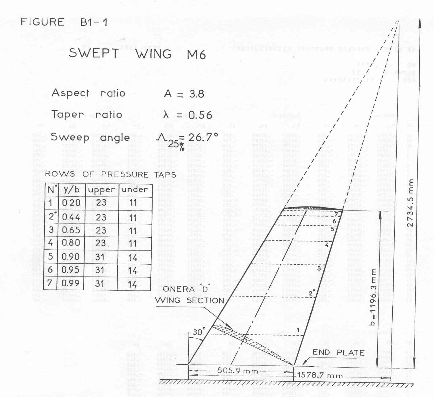
Figure 2. Geometric layout of the ONERA M6 wing (Fig. B1-1 from
reference 1.).
| Span, b | 1.1963 meters |
|---|---|
| Mean Aerodynamic Chord, c | 0.64607 meters |
| Aspect Ratio | 3.8 |
| Taper Ratio | 0.562 |
| Leading-edge Sweep | 30.0 degrees |
| Trailing-edge Sweep | 15.8 degrees |
Comparison data consists of pressure coefficients at sections along the span of the wing obtained in the experiment performed by Schmitt and Charpin as reported in the AGARD report referenced below. Table 3 lists links to text data files containing these pressure coefficients along the lower and upper surfaces of the wing at each of the seven sections. The spanwise location of the sections are specified with respect to the wing span, b. The accuracy of the pressure coefficient measurements at Mach 0.84 was determined to be +/- 0.02.
| Section | y/b | Cp Lower Surface | Cp Upper Surface |
|---|---|---|---|
| 1 | 0.2 | cp1l.ex | cp1u.ex |
| 2 | 0.44 | cp2l.ex | cp2u.ex |
| 3 | 0.65 | cp3l.ex | cp3u.ex |
| 4 | 0.8 | cp4l.ex | cp4u.ex |
| 5 | 0.9 | cp5l.ex | cp5u.ex |
| 6 | 0.95 | cp6l.ex | cp6u.ex |
| 7 | 0.99 | cp7l.ex | cp7u.ex |
The experimental pressure coefficients are also available in a TECPLOT data file, ONERAb114.tec.
| Study | Category | Person | Comments |
|---|---|---|---|
| Study #1 | Example | J.W. Slater | Demonstrate computation for a 3D wing flow. |
| Study #2 | Verification | J.W. Slater | Verify zero drag about 3D wing in inviscid flow. |
The AIAA Paper 97-2010 referenced below by Mani et al. presents computational results for this case obtained using NASTD (predecessor to WIND) as part of an assessment of the Spalart-Allmaras and SST turbulence models.
1. Schmitt, V. and F. Charpin, "Pressure Distributions on the ONERA-M6-Wing at Transonic Mach Numbers," Experimental Data Base for Computer Program Assessment. Report of the Fluid Dynamics Panel Working Group 04, AGARD AR 138, May 1979.
2. Mani, M., J.A. Ladd, A.B. Cain, and R.H. Bush, "An Assessment of One- and Two-Equation Turbulence Models for Internal and External Flows", AIAA 97-2010, June 1997.