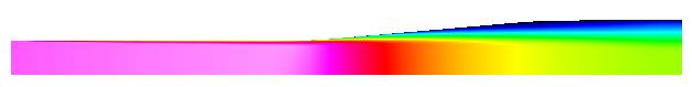
Figure 1. Mach number shading for turbulent flow in the Fraser Subsonic Diffuser.
Figure 1. Mach number shading for turbulent flow in the
Fraser Subsonic Diffuser.
This validation case examines the turbulent, subsonic flow in a pipe attached to a conical diffusing section. Table 1 lists the flow conditions for the inflow. The Reynolds number is based on the diameter of the pipe. These conditions are referred to as the Fraser (Flow A) case from the 1968 AFOSR-IFP Stanford Conference on Computation of Turbulent Boundary Layers.
| Mach | 0.15 |
|---|---|
| Reynolds Number (based on diameter) | 500000 |
| Angle-of-Attack (degrees) | 0.0 |
| Angle-of-Sideslip (degrees) | 0.0 |
The geometry consists of a straight section of pipe followed by a 5 degree half-angle conical diffuser. The coordinates of the diffuser are listed as axial (x) and radial (r) pairs in the file geom.xr.gen. The coordinates are in units of meters.
The computational domain is bounded by the inflow plane, diffuser surface, axis-of-symmetry and the outflow plane.
Comparison data consists of pressure and skin friction coefficient along the inner surface of the duct. The pressure coefficients are contained in the GENPLOT file cp.data.gen. The skin friction coefficients are contained in the file cf.data.gen. The first column of both files is the axial coordinate (x) in units of meters.
The pressure coefficient Cp is defined as
Cp = ( p - pref ) / qrefwhere qref is the dynamic pressure at the reference state,
qref = 0.5 rhoref u2ref
The reference state is the conditions at the centerline at the entrance to the diffusing section ( x = 0.001 meters ). These conditions are listed in Table 1.
The skin friction coefficient Cf is defined as
Cf = (tau)wall / qrefThe (tau)_wall is the skin friction at the wall and is defined as
(tau)_wall = mu du/drwallwhere mu is the viscosity and du/drwall is the velocity gradient normal to the wall.
Additional data files include: 1) the displacement thickness along the diffuser disp.gen, 2) the momentum thickness thet.gen, 3) the shape factor shape.gen, 4) velocity profiles at station 0.119 meters vel.119.gen, 0.381 meters vel.381.gen, and 0.642 meters vel.642.gen.
| Study | Category | Person | Comments |
|---|---|---|---|
| Study #1 | Validation | J.C. Dudek | Application of internal subsonic turbulent flow. |
| Study #2 | Validation | J.W. Slater | Re-baseline to WIND 3.0. |
Fraser, H.R., "The Turbulent Boundary Layer in a Conical Diffuser," Journal of the Hydraulic Division , Proceedings of the American Society of Civil Engineers, pp. 1684-1-17, June 1958.
Dudek, J.C., N.J. Georgiadis, and D.A. Yoder, "Calculation of Turbulent Subsonic Diffuser Flows Using the NPARC Navier-Stokes Code," AIAA Paper 96-0497, January 1996.