At the end of the summer of 1901, the Wright brothers were frustrated by the flight
tests of their 1901 glider.
The aircraft was flown frequently up to 300 feet in a single glide. But the
aircraft did not perform as well as the brothers had expected.
The aircraft only developed 1/3 of the lift
which was predicted by the
lift equation
using Lilienthal's data.
During the fall of 1901, the brothers began to question the aerodynamic
data on which they were basing their designs. So, they decided to
conduct a series of
wind tunnel tests
to verify the results they were
experiencing
in flight.
They would measure the aerodynamic lift and drag
on small models of their wing designs using a
wind tunnel
in their bicycle shop at Dayton, Ohio.
They built two separate balances to perform these measurements,
one for lift and the other for
drag.
On this page we will discuss
the design of the lift balance and on a separate page
we will discuss the
procedure
the brothers used to obtain data from the balance.
Because of the form of the
lift equation
used by the brothers, they were interested in measuring
the lift generated by a model relative to the drag of a reference flat plate.
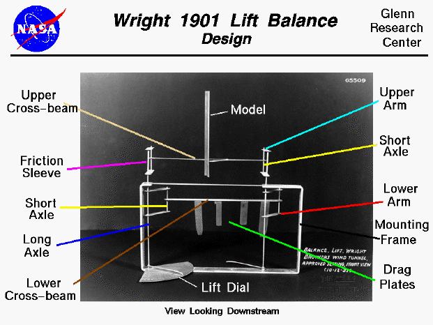
On the slide we show a photo of a reconstruction of the lift balance with the
parts indicated by colored leader lines.
The actual balance was made from bicycle spokes and hacksaw blades and was a
very delicate instrument.
We are looking downstream inside the tunnel, so the wind would strike
the model in the direction that you are looking.
The balance is attached to the floor of the tunnel by a screw through
the mounting frame (black). It could then be easily removed and
replaced in the tunnel by the drag balance.
On the lower cross beam (dark brown) the reference
drag plates (green) are permanently attached.
The cross beam is rigidly attached to short vertical axles (yellow) on each end.
The vertical axles are loosely attached to arms (red) at the top and bottom
so that the cross beam can move from side to side.
The arms are rigidly attached to
long axles (blue) that run through the mounting frame.
The long axles are free to rotate in the frame as the lower cross beam moves.
The arrangement of the axles and arms cause the ends of lower cross beam to move
in circular arcs about the long axles with the cross beam always parallel to
the bottom of the frame.
At the bottom of the left long axle, a pointer is rigidly attached
perpendicular to the arms. This
pointer indicates the amount of rotation of the long axles on a dial
at the bottom of the left axle.
The upper cross beam (light brown) is also rigidly attached to short axles (yellow)
which are loosely attached to the upper arms (cyan). These arms are attached
to the long axle by a friction sleeve (purple). When the friction
sleeve is engaged, the long axle rotates and the lower cross beam
moves as the upper cross beam is moved.
When the friction sleeve is dis-engaged, you can move the upper cross
beam without moving the lower cross beam or long axle.
The wing
model
is attached to the balance
on the upper cross beam. The
angle of attack
of the model is varied between tests by pivoting the model on the
bracket which attaches it to the cross beam.
The brothers built models
from strips of 20 guage steel (1/32 inch thick) which were
cut, hammered, filed and soldered to produce various shapes.
They made between one and two hundred models and
made quick preliminary tests in
October, 1901, to develop their
test techniques
and to investigate a wide range of design variables.
Some of the models were used in combination to study bi- and tri-wing designs.
Following the preliminary experiments, they chose about 30 of their
best designs for more detailed testing.
The models were numbered by the brothers
and each was designed to be part of a
parametric study of lift and drag by changing
the value of only one design variable between models.
The actual balance and models are currently kept at
The Franklin Institute.
You can simulate the operation of the lift balance by using our
interactive tunnel simulator.
Navigation..


- Beginner's Guide Home Page
|
