 |
|
Glenn
|
|
|
|
Glenn
|
Most modern passenger and military aircraft are powered by gas turbine engines, which are also called jet engines. There are several different types of gas turbine engines, but all turbine engines have some parts in common. All gas turbine engines have a power turbine located downstream of the burner to extract energy from the hot flow and turn the compressor. Work is done on the power turbine by the flow; the mathematical details of this process are given on a separate slide. There is also a picture slide that shows photographs of actual turbines.
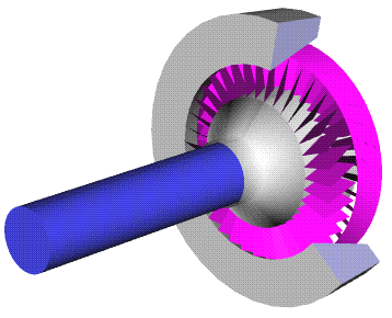
Description of Image
In this figure we show a computer animation of a power turbine. The turbine is magenta colored; the central shaft is blue. The front (left end) of this shaft would be attached to the compressor. The turbine, like the compressor, is composed of two rows of airfoil cascades. One row, called the rotor, is connected to the central shaft and rotates at high speed. The other row, called the stator, is fixed and does not rotate. The job of the stators is to keep the flow from spiraling around the axis by bringing the flow back parallel to the axis.
Depending on the engine type, there may be multiple turbine stages present in the engine. Turbofan and turboprop engines usually employ a separate turbine and shaft to power the fan and gear box respectively. Such an arrangement is termed a two spool engine. For some high performance engines, an additional turbine and shaft can be present to power separate parts of the compressor. This arrangement produces a three spool engine.
Design Details
There are several interesting turbine design details present on this slide. Since the turbine extracts energy from the flow, the pressure drops across the turbine. This pressure gradient helps keep the flow attached to the turbine blades. So the pressure drop across a single turbine stage can be much greater than the pressure increase across a corresponding compressor stage. A single turbine stage can be used to drive multiple compressor stages. To keep flow from leaking around the edges of the turbine blades, because of the higher pressure gradient, the tips of the turbine blades may be banded together.
The turbine blades exist in a much more hostile environment than compressor
blades. Sitting just downstream of the burner, the blades experience flow temperatures
of more than a thousand degrees Fahrenheit. Turbine blades must, therefore,
be made of special metals that can withstand the heat. Or they must be actively
cooled.
![]()
![]()
![]()
![]()
Go to...
byTom
Benson
Please send suggestions/corrections to: benson@grc.nasa.gov