
An animated version of this slide is also available.
Most modern passenger and military aircraft are powered by gas turbine engines, which are also called jet engines. Jet engines come in a variety of shapes and sizes but all jet engines have certain parts in common.
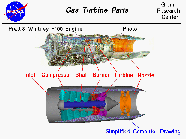
At the top of this slide we have a picture of a Pratt and Whitney F100 jet engine, which is used in the F15 and F16 fighter aircraft. As we can see in the picture, jet engines are complicated pieces of machinery. Jets have a lot of parts which spin on a central shaft. To enclose the spinning parts, a jet engine is shaped like a long cylinder. At the bottom of the slide we have a much simpler computer drawing of the engine parts. On the animated version of this slide you can take the "computer" engine apart to look at the pieces and see how they go together.
In the computer drawing, we have cut out a portion of the engine to have a look inside. Various parts on the photograph are labeled and the corresponding parts on the computer drawing are indicated. At the front of the engine, to the left, is the inlet which brings outside air into the engine. The F100 engine picture does not show the aircraft inlet because the inlet is part of the airframe and changes from aircraft to aircraft. At the exit of the inlet is the compressor, which is colored cyan. The compressor is connected by a blue colored shaft to the turbine, which is colored magenta. The compressor and the turbine are composed of many rows of small airfoil shaped blades. Some rows are connected to the inner shaft and rotate at high speed, while other rows remain stationary. The rows that spin are called rotors and the fixed rows are called stators. The combination of the shaft, compressor and turbine is called the turbomachinery. Between the compressor and the turbine flow path is the combustion section or burner, which is colored red. This is where the fuel and the air are mixed and burned. The hot exhaust then passes through the turbine and out the nozzle. The nozzle performs two important tasks. The nozzle is shaped to accelerate the hot exhaust gas. The nozzle is also used to set the mass flow rate through the engine. The thrust equation indicates that the change in velocity (acceleration) times the mass flow rate determines the thrust of the engine. The F100 is an afterburning turbofan engine and the flame holders for the afterburner are shown in orange in the nozzle of the drawing. (The front section of the F100 is the fan section which is not modeled on the computer drawing.)
To analyze jet engine operation, engineers have adopted a numbering scheme for the various parts. This scheme and the accompanying two-dimensional schematic drawing are given on a separate slide.
You can investigate the effects of the various engine parts on jet engine operation by using the EngineSim interactive Java applet. You can vary the performance of any of the engine parts and investigate the effects on thrust and fuel flow.
Go to...
byTom
Benson
Please send suggestions/corrections to: benson@grc.nasa.gov