
|
Aerodynamic Force Model
|
Glenn
Research
Center
|
Aerodynamicists use
wind tunnels
to test models of proposed
aircraft and engine components. The model is placed in the test section of the tunnel
and air is made to flow past the model.
In some wind tunnel tests, the
aerodynamic forces on the model are measured.
In some wind tunnel tests, the model is instrumented to provide diagnostic
information about the flow of air around the model. Model instrumentation
can include
static pressure taps,
tufts on the surface, or
total pressure rakes.
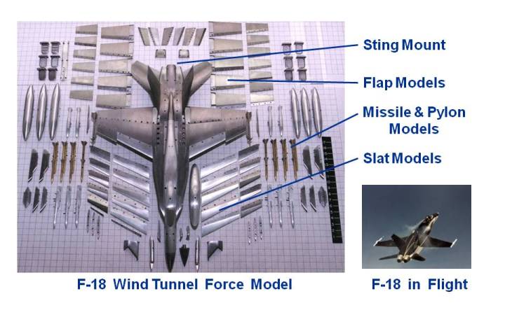
Wind tunnel models are complex and expensive pieces of equipment. The photo at the
top left of the page shows an F-18 airframe model. Comparing with the smaller F-18 in-flight picture,
we see that the model must duplicate all of the geometric lines of the aircraft that is being modeled.
The F-18 carries a wide variety of external stores which must also be carefully modeled. In the model photo,
we see a variety of missile and fuel tank models in addition to the pylons
that hold the stores on the wing. The
wing of the F-18 includes
flaps and slats
to improve low speed performance during aircraft carrier landings. Looking carefully at the photo,
we see several pieces of wing leading edges (slats) and trailing edges (flaps) that must be attached
to the airframe to properly model a specific wing geometry.
During the test, the wind tunnel must be
stopped to allow technicians to enter the test section and modify the model for the various geometries.
Then the tunnel must be re-started and brought up to test conditions with the new geometry.
To save test time, variable geometry is sometimes built into the model.
Small actuators in the model are used to move pieces on the model that would also move on
the full scale aircraft.
While variable geometry saves test time, a variable geometry model is often more expensive
than a model with multiple pieces.
The small actuators for the model must work with precision to properly model the proposed aircraft and the
model must be remotely controlled and modified from the control room.
Looking closely at the model photo, we notice that the rear of the aircraft (top of the photo) has been
distorted to provide a mounting sting for the model. Here is a picture of this model mounted in
the 12 foot wind tunnel at NASA Ames. The view is from the back, looking upstream into the tunnel.
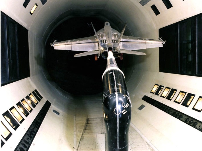
Notice that the rear of the model is distorted relative to the actual F-18 design.
The actual F-18 has twin engine exhausts at the rear
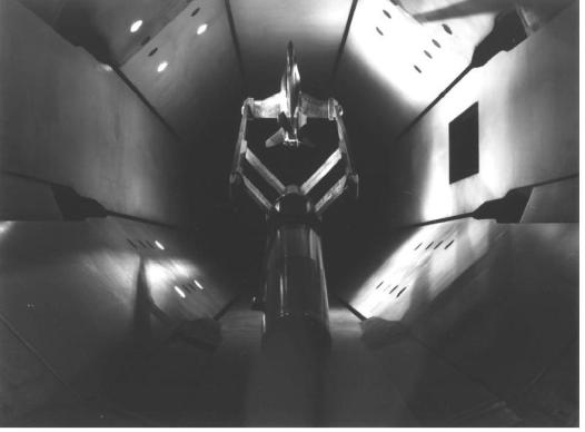
of the aircraft as shown in the small in-flight photo. To accurately predict the drag of the aircraft,
corrections must be applied to the data from the airframe test to account for the nozzle exhaust. Often,
a special model is used in which the aircraft is mounted by the wing tips and the afterbody and nozzles
are correctly modeled. Here is a photo of an F-18 nozzle/afterbody model mounted in the NASA
Langley 16 foot tunnel.
Multiple models are often required to determine the aerodynamic forces on a proposed aircraft for
all of the geometric and flight conditions.
Navigation ..


- Beginner's Guide Home Page
|