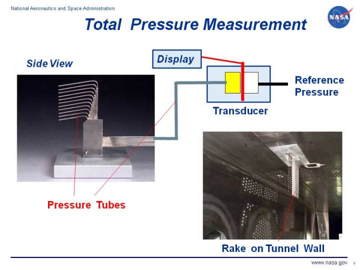
This page shows two photographs of a total pressure
boundary layer rake.
The rake is used for
diagnostic wind tunnel testing
to determine the
total pressure
distribution along the wall of a model or within the tunnel itself.
At the lower right of the figure, we show the rake mounted on the wall of a
wind tunnel.
At the upper left, we show a photo of the rake itself. The rake is a series of
small parallel tubes that are aligned with the flow direction.
Because each tube is aligned with the flow, the tube is pressurized by both the random
component and the ordered component of the air velocity. The pressure in the tube is the
total pressure as discussed in
Bernoulli's equation.
Within a
boundary layer,
the static pressure is a constant value that is determined by the flow outside the boundary
layer. The velocity varies from its free stream value to zero at the wall. The
total pressure also varies from free stream to the wall in the same way that the velocity
varies. By measuring the total pressure variation with a rake, the engineer can determine
the thickness and state of the boundary layer on a model or within the tunnel.
To measure the total pressure, long thin tubes connect the rake tubes to a
pressure transducer
located outside of the wind tunnel model. In this figure, the transducer is shown
in a schematic drawing.
The transducer measures the difference in pressure between the pressure in the tube
and a reference pressure by measuring the strain on a thin element using
an electronic
strain gauge, shown in red on the drawing.
The reference pressure is arbitrary, but should be noted in any data report. Possible reference
pressures include the external free stream value or the wind tunnel total pressure.
Either an average, steady state pressure, or a time-varying, unsteady pressure value can be obtained
depending on the capabilities of the transducer.
Looking at the picture of the rake, on the left, we see that diagnostic models are
complex, precise, and normally quite expensive pieces of equipment. The model must be
carefully
designed
to place the rake where it can provide the most
information
to the engineer.
Routing pressure taps to the transducer is obviously a challenging engineering and
manufacturing problem.
In some applications, a bundle of five pitot tubes are arranged to form a
five hole probe.
A five hole probe can be used to determine the flow angularity at a given location
on a wind tunnel model. It can also be used to determine the angle of attack and yaw
on a flying aircraft or rocket.
Navigation ..


- Beginner's Guide Home Page
|