Most modern passenger and military aircraft are powered by
gas turbine engines, also called jet
engines. The first and most simple type of
gas turbine is the turbojet. In the
turbojet engine, large amounts of the surrounding air are brought
into the engine through the inlet. The air
pressure and temperature are increased by the compressor,
which performs work on the flow. In the burner
the air is mixed with a small amount of fuel and ignited. The hot
exhaust is then passed through the turbine.
The turbine takes some energy out of the hot exhaust in order to turn
a shaft which powers the compressor. But there is
enough energy left over to provide thrust to the jet engine by
increasing the velocity through the nozzle.
Separate pages describe the thermodynamics and performance aspects
of the inlet, compressor,
burner, turbine,
and nozzle. The pressure variation
EPR and temperature variation ETR
through the engine can be determined if we know the individual
component performances. The total engine performance, thrust
and fuel consumption, can then be easily
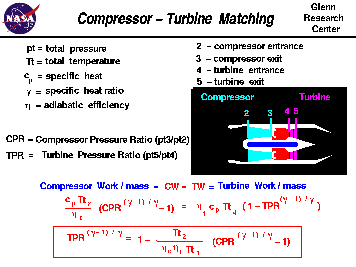
determined. The task is simplified (a little) because the compressor
and turbine are coupled together by the main shaft.
The work done by the turbine must equal the work required
by the compressor. On this slide we reproduce the work equations from
the component slides and then simplify the equation to solve for the
turbine pressure ratio TPR in terms of the compressor
pressure ratio CPR, the total temperature at the compressor
face Tt2 or free stream total temperature, and the total
temperature at the turbine entrance Tt4.
The compressor work CW equation is given as:
CW = cp * Tt2 * (CPR ^((gam - 1) / gam) - 1) / nc
Where cp is the
specific heat coefficient at constant pressure,
gam is the ratio of specific heats, and nc is the compressor efficiency.
The turbine work TW equation is given by:
TW = nt * cp * Tt4 * (1 - TPR ^ ((gam -1) / gam))
where nt is a turbine efficiency factor.
Equating and solving for TPR:
TPR ^ ((gam -1) / gam) = 1 - Tt2 * (CPR ^((gam -1) / gam) - 1) / (nc * nt * Tt4)
We can use this equation in two ways. We can specify the pressure
increase across the compressor to determine the pressure loss through
the turbine. Or, if we know the pressure loss across the turbine, we
can solve for the pressure increase through the compressor. The first
use of the equation is employed in preliminary engine design, while
the second use is employed in determining "off-design" performance.
Every engine is designed around some set of desired conditions. Those
conditions might include the size of the engine, the thrust at
takeoff, or the maximum thrust at some prescribed altitude. At the
design condition, we can select values of the important thermodynamic
variables: the maximum burner temperature, the CPR, and the nozzle
area. All other flight conditions, speed and altitude, and throttle
setting will be "off-design." For an existing engine, the pressure
loss across the turbine can be determined by the airflow through the
nozzle and the throttle setting Tt4, as shown on a separate
slide. From the above equation, we can then determine the compressor
pressure ratio.
Activities:
Guided Tours
-
 EngineSim - Engine Simulator:

Navigation ..

- Beginner's Guide Home Page
|
