Most modern passenger and military aircraft are powered by
gas turbine engines, which are also called
jet engines. There are several different types
of gas turbine engines, but all turbine engines have some parts
in common. All turbine engines have an inlet to bring
free stream air into the engine. The inlet
sits upstream of the compressor and,
while the inlet does no work on the flow,
inlet performance
has a strong influence on engine net
thrust.
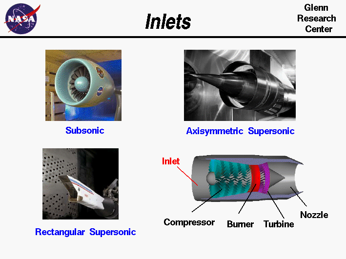
As shown in the figures above, inlets come in a variety of
shapes and sizes with the specifics usually dictated by the speed of
the aircraft.
SUBSONIC INLETS
For aircraft that cannot go faster than the
speed of sound,
like large airliners, a simple, straight, short inlet
works quite well. On a typical
subsonic
inlet, the surface of the inlet
from outside to inside is a continuous smooth curve with some
thickness from inside to outside. The most upstream
portion of the inlet is called the highlight, or the inlet
lip. A subsonic aircraft has an inlet with a relatively thick
lip.
SUPERSONIC INLETS
An inlet for a
supersonic
aircraft, on the other hand, has a
relatively sharp lip. The inlet lip is sharpened to minimize the
performance losses from
shock waves
that occur during supersonic
flight. For a supersonic aircraft, the inlet must slow the flow down
to subsonic speeds before the air reaches the compressor. Some
supersonic inlets, like the one at the upper right, use a central
cone to shock the flow down to subsonic speeds. Other inlets, like
the one shown at the lower left, use flat hinged plates to generate
the compression shocks, with the resulting inlet geometry having a
rectangular cross section. This variable geometry inlet is
used on the F-14 and
F-15 fighter aircraft. More exotic inlet shapes are used
on some aircraft for a variety of reasons.
The inlets of the
Mach 3+
SR-71 aircraft are specially designed to allow
cruising flight at high speed.
The inlets of the SR-71 actually produce thrust during flight.
HYPERSONIC INLETS
Inlets for
hypersonic
aircraft present the ultimate design challenge. For
ramjet-powered
aircraft, the inlet must bring the high speed external flow
down to subsonic conditions in the
burner. High stagnation temperatures are present
in this speed regime and variable geometry may not be an option for the
inlet designer because of possible flow leaks through the hinges.
For
scramjet-powered
aircraft, the heat environment is even worse because the flight
Mach number is higher than that for a ramjet-powered aircraft.
Scramjet inlets are highly integrated with the fuselage of the
aircraft. On the X-43A, the inlet includes the entire lower
surface of the aircraft forward of the cowl lip. Thick, hot
boundary layers
are usually present on the compression surfaces of hypersonic inlets.
The flow exiting a scramjet inlet must remain supersonic.
INLET EFFICIENCY
An inlet must operate efficiently over the entire flight envelope
of the aircraft. At very low aircraft speeds, or when just sitting on
the runway, free stream air is pulled into the engine by the
compressor. In England, inlets are called intakes, which is a
more accurate description of their function at low aircraft speeds.
At high speeds, a good inlet will allow the aircraft to maneuver to
high
angles of attack
and sideslip without disrupting flow to the
compressor.
Because the inlet is so important to overall aircraft
operation, it is usually designed and
tested
by the airframe company,
not the engine manufacturer. But because inlet operation is so
important to engine performance, all engine manufacturers also employ
inlet aerodynamicists.
The amount of disruption of the flow is characterized
by a numerical
inlet distortion index.
Different airframers use
different indices, but all of the indices are based on ratios of the
local variation of pressure to the average pressure at the compressor face.
The ratio of the average total pressure at the compressor face to the
free stream total pressure is called the
total pressure recovery.
Pressure recovery is another inlet performance
index; the higher the value, the better the inlet. For hypersonic inlets
the value of pressure recovery is very low and nearly constant because of
shock losses, so hypersonic inlets are
normally characterized by their kinetic energy efficiency.
If the airflow demanded by the engine is much less than the airflow
that can be captured by the inlet, then the difference in airflow is
spilled around the inlet. The airflow mis-match can produce spillage
drag on the aircraft.
Activities:

Guided Tours
-
 Parts of a Jet Engine:

-
Inlet:
-
Turbojets:
-
Afterburning Turbojets:
-
Turbofans:
-
Ramjets:
Navigation ..


- Beginner's Guide Home Page
|