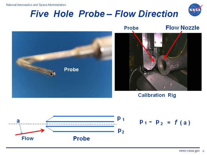
This page shows two photographs of a
five hole probe.
The probe is used for
diagnostic wind tunnel testing
and in flight testing
to determine the flow direction or angularity.
At the upper left of the figure, we show a picture of the probe itself.
The probe is a bundle of five tubes; a center tube surrounded by
four tubes in the shape of a cross. The leading edge of the four outside tubes are
cut at a 45 degree angle to the center tube.
At the bottom left is a diagram of the probe with a vertical cut through three of the tubes,
shown in blue. The flow of air past the probe
makes an angle a with the centerline of the center probe. If the angle was zero,
all three probes would act as
pitot tubes
and transducers at the end of the tubes would record the
total pressure
of the flow. If the angle is not zero, the probe on the bottom detects a pressure p2
that is different than the pressure p1 on the top. The difference is caused by the
dynamic pressure
associated with the velocity of the flow.
The difference in pressure between the top and bottom probes is some function of the angle
of the flow:
p1 - p2 = f (a)
We can determine the form of the function by calibrating the probe. A calibration rig is shown
in the picture at the upper right of figure. Axial flow is generated by the flow nozzle. The probe
is inserted into the flow and the angle that the probe makes with the flow is
varied during the calibration test. A mathematical calibration curve is then generated for the
measured difference in pressure as a function of the measured angle.
The diagram at the left shows a vertical cut through three of the tubes. The angle of the flow a
is then related to the
angle of attack
of an aircraft.
A similar horizontal cut can be made through the two remaining tubes and the angle of the flow
is then related to the
yaw angle
of an aircraft. A five hole probe can therefore be used to simultaneously provide both pitch and yaw
information in a flight test, or to provide the flow angularity in two perpendicular planes in a
wind tunnel test. There are three hole probes that can also be used if we are only interested in the
flow deflection in one direction.
During a wind tunnel or flight test, the probe is inserted into the flow and aligned relative to some
part of the tunnel or aircraft. Using the measurements from the five tubes and the calibration curves,
we can determine the deflection of the flow in two perpendicular planes relative to the wind tunnel
or aircraft part. In some applications, the probe may be moved through the flow field to develop a
complete map of the flow angularity. But in most applications, the probe remains fixed to the tunnel
wall, model, or flight vehicle.
Navigation ..


- Beginner's Guide Home Page
|