|
This page is intended for college, high school, or middle school students.
For younger students, a simpler explanation of the information on this page is
available on the
Kids Page.
|

Most modern passenger and military aircraft are powered by
gas turbine engines, which are also called
jet engines. There are several different types
of gas turbine engines, and all turbine engines have some parts
in common. All turbine engines have a combustor, or
burner, in which the fuel is combined with high pressure air
and burned. The resulting high temperature
exhaust gas is used to turn the power
turbine and produce thrust when passed
through a nozzle.
Burners are also used on
ramjet and
scramjet
propulsion systems. The design of ramjet and scramjet burners are slightly
different than the burners used on gas turbine engines, although the
basic
thermodynamic principles
are the same.
On this page, we discuss the operation of a gas turbine burner.
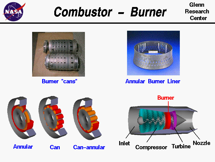
The burner is shown in red on the computer graphic at the lower right
of the figure. The burner sits between the compressor
and the power turbine. The burner is arranged like an annulus,
or a doughnut, as shown by the three burner configurations at the
lower left. The central shaft that connects the turbine and
compressor passes through the center hole. Burners are made from
materials that can withstand the high
temperatures
of combustion.
A burner usually has an outer casing, shown in red, and an inner liner,
shown in orange. The liner is often perforated to enhance mixing of
the fuel and air, as shown in the photo at the upper right.
There are three main types of combustors, and all three designs
are found in modern gas turbines:
- The burner at the left is an annular combustor with the
liner sitting inside the outer casing which has been peeled open
in the drawing. Many modern burners have an annular design.
- The burner in the middle is an older can or tubular
design. The photo at the top left shows some actual burner cans.
Each can has both a liner and a casing, and the cans are arranged
around the central shaft.
- A compromise design is shown at the right. This is a
can-annular design, in which the casing is annular and the
liner is can-shaped. The advantage to the can-annular design is
that the individual cans are more easily designed, tested, and serviced.
The details of mixing and burning the fuel are quite complex and
require extensive testing for a new burner. For our purposes, we can
consider the burner as simply the place where combustion
occurs and where the working fluid (air) temperature is raised with a
slight decrease
in pressure.
Activities:


Guided Tours
-
 Parts of a Jet Engine:

-
 Burner:

-
 Turbojets:

-
 Afterburning Turbojets:

-
 Turbofans:

Navigation ..


- Beginner's Guide Home Page
|
