Most modern passenger and military aircraft are powered by
gas turbine engines, which are also called
jet engines. There are several different types
of jet engines, but all jet engines have some partsin common.
All jet engines have an inlet to bring
free stream air into the engine. The inlet sits upstream of the
compressor and, while the inlet does no
work on the flow, there are some important design features of the
inlet.
Because the inlet does no
thermodynamic work,
the total temperature through the inlet is constant.
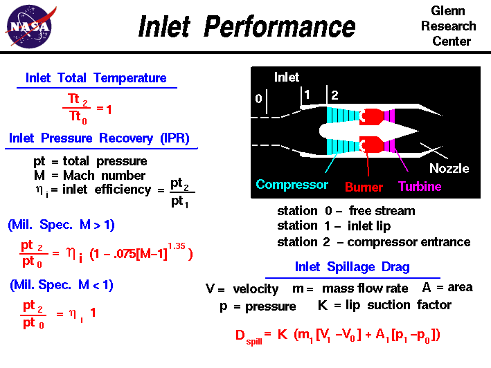
Referring to our station numbering,
free stream conditions are noted by a "0" subscript, the entrance to the inlet
is station "1" and the exit of the inlet and entrance to the compressor is
station "2". The inlet total temperature Tt ratio is
Tt2 divided by Tt0 and is equal to 1.0
Tt2 / Tt0 = 1
The total pressure pt through the inlet changes, however, because
of several flow effects. Aerodynamicists characterize the inlet's
pressure performance by the inlet total pressure recovery,
which measures the amount of the free stream flow conditions that are
"recovered". The pressure recovery pt2 / pt0 depends on a wide variety offactors, including the shape of the inlet, the speed of the aircraft,
the airflow demands of the engine, and aircraft maneuvers. On the
slide we show some simple equations for the pressure recovery that
are used as standards.
Recovery losses associated with the
boundary layers
on the inlet surface or flow separations in the duct are included in
the inlet efficiency factor ni:
ni = pt2 / pt1
For
subsonic flight
speeds, these losses are
the only losses. For
Mach number M less than 1, the Military
Specifications (Mil. Spec.) value of recovery is the inlet efficiency:
Mil. Spec., M < 1 : pt2 / pt0 = ni * 1
At supersonic flight
speeds, there are additional
losses created by the
shock waves
necessary to reduce the flow speed
to subsonic conditions for the compressor. The magnitude of the
recovery loss depends on the specific inlet design and is usually
determined experimentally.
Mil. Spec., M > 1 : pt2 / pt0 = ni * ( 1 - .075 * [M - 1] ^1.35)
The Mil. Spec. loss is a good first
estimate of inlet recovery. Actual inlet performance may be
greater, but is usually less than Mil. Spec.
There is an additional propulsion performance penalty charged
against the inlet called spillage drag. Spillage drag, as the
name implies, occurs when an inlet "spills" air around the outside
instead of conducting the air to the compressor face. The amount of
air that goes through the inlet is set by the engine and changes
with altitude and throttle setting. The inlet is usually sized to
pass the maximum airflow that the engine can
ever demand and, for all other conditions, the inlet spills the
difference between the actual engine airflow and the maximum air
demanded. As the air spills over the external cowl lip, the air
accelerates and the pressure decreases. This produces a
lip suction effect that partially cancels out the drag due to spilling.
Inlet aerodynamicists account for this effect with a correction
factor K that multiplies the theoretical spillage drag. Typical
values of K range from .4 to .7. But for a given inlet the value is
determined experimentally. The form of the theoretical spillage drag D spill
is very similar to the thrust equation,
with a mass flow m dot times velocity term V and a
pressure p times area A term:
D spill = K * (mdot i * [V1 - V0] + A1 * [p1 - p0])
As the air is brought from free stream to the compressor face, the
flow may be distorted by the inlet. At the
compressor face, one portion of the flow may have a higher
velocity or higher pressure than another portion. The flow may be
swirling, or some section of the boundary layer may be thicker than
another section because of the inlet shape. The rotor blades of the
compressor move in circles around the central shaft. As the blades
encounter distorted inlet flow, the flow conditions around the blade
change very quickly. The changing flow conditions can cause flow
separation in the compressor, a compressor stall, and can
cause structural problems for the compressor blades. A good inlet
must produce high pressure recovery, low spillage drag, and low
distortion.
You can investigate the effects of inlet performance on total engine
performnace by using the
EngineSim
computer program. Click on "Inlet" on the graphics panel and vary
te amount of inlet recovery. Because an inlet is essentially a hollow
tube, the weight considerations of the inlet are small compared to the
compressor or turbine. For ramjet and scramjet inlets, the
materials
used in the inlet must withstand high temperatures.
Activities:

Guided Tours
-
 EngineSim - Engine Simulator:

-
Inlet:
Navigation ..


- Beginner's Guide Home Page
|