For the forty years following the
first flight
of the Wright brothers, airplanes used
internal combustion engines
to turn
propellers
to generate
thrust.
Today, most general aviation or private airplanes are still
powered by propellers and internal combustion engines, much like your
automobile engine.
On this page we will discuss the fundamentals of the
internal combustion engine using the
Wright brothers' 1903 engine, shown in the figure, as an example.
The brothers' design is very simple by today's standards, so it is a good
engine for students to study to learn the fundamentals of
engine operation. This type of
internal combustion engine
is called a
four-stroke
engine because there are four movements
(strokes)
of the piston before the entire engine firing sequence is repeated.
In the figure, we have colored the
fuel/air intake system
red, the
electrical system
green, and the
exhaust system
blue. We also represent the fuel/air mixture and the exhaust gases by small
colored balls to show how these gases move through the engine.
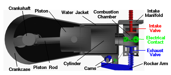
Since we will be referring to the movement of various engine parts, here is
a figure showing the names of the parts:
Mechanical Operation
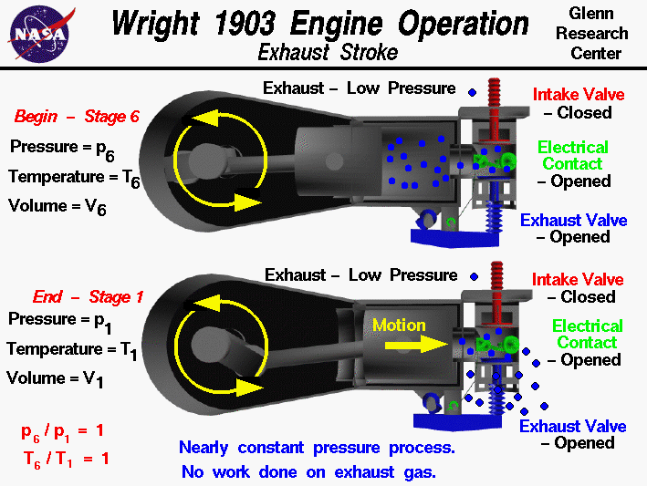
At the end of the
heat rejection
process, the piston is at the far left and exhaust gas has been cooled
to nearly atmospheric conditions. The exhaust valve is then opened
to begin the exhaust stroke.
The purpose of the exhaust stroke is to
clear the cylinder of the spent exhaust in preparation for another
ignition
cycle.
The exhaust stroke
begins at
Stage 6
as the piston is
pushed towards the combustion chamber (to the right in the figure).
The intake valve is closed, the electrical contact is open,
and the exhaust valve is opened
by the cam pushing on the rocker arm.
The exhaust gas is pushed past the valve and exits the engine.
At the end of the exhaust stroke,
Stage 1,
the piston is located at the far right and is ready
to begin another
intake stroke
after the exhaust valve is closed and the intake valve is opened.
Thermodynamics
The exhaust stroke takes place at a nearly constant atmospheric pressure
because the exhaust valve is open to the atmosphere throughout
the stroke.
There is (theoretically) no
work
done on the exhaust during this process.
The random motion of the gas causes to exit the combustion chamber and
cylinder as the volume is decreased by the piston motion.
The pressure and temperature ratios are both 1.0 during the exhaust stroke.
Activities:
Guided Tours
Navigation..


- Beginner's Guide Home Page
|