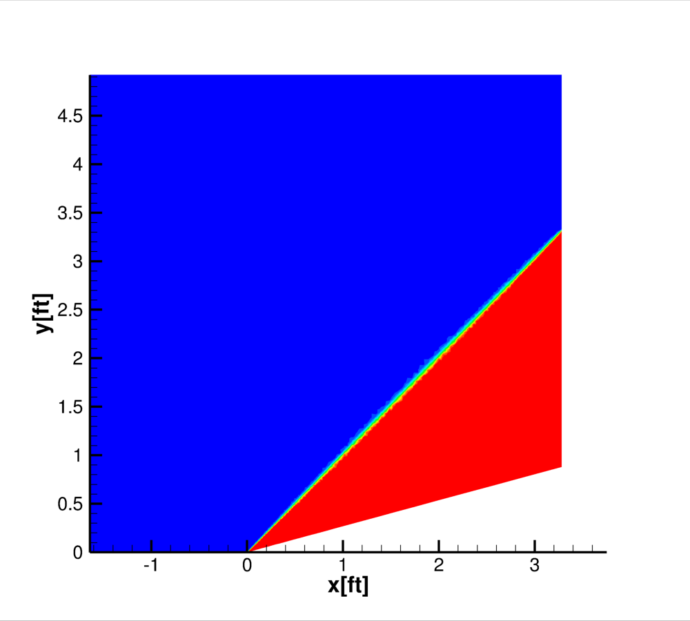
Figure 1. Pressure contours of the Mach 2.0 15 degree wedge
Figure 1. Pressure contours of the Mach 2.0 15 degree wedge
Mach 2.0 flow over a 15 degree wedge was used to test the Wind code's ability to compute supersonic inviscid flows and in particular to capture shock waves.
| Wind-US 3.146 |
|---|
| wedge.tar |

Figure 2. 2D view of the grid

Figure 3. 3D view of the grid
The unstructured grid was generated using GridGen. The shock position was computed using inviscid theory and grid points were clustered around this line. The grid was developed as a two-dimensional plane and then extruded to three dimensions for Wind-US. The grid consists of 4,884 points.
After the cgd file was exported from Gridgen, CFPART was used to add lines to the grid in preparation to be solved with Wind-US3.146. In Table 1, both the Common and Gridgen versions of the grid are attached as well as the CFPART script used to add lines.
| Pre-processing | Common Grid | Gridgen | |
|---|---|---|---|
| File | cfpart.inp | wedge.cgd | wedge.gg |
| Pressure (psia) | Temperature (R) | Mach Number | |
| Freestream | 14.7 | 520 | 2.0 |

Figure 4. Boundary conditions. Note: This is a 2D view of the 3D grid. Inviscid walls were specified on the sidewalls/xy-planes.
Monitoring the residuals was used to determine the convergence of this case. Below are the algorithm settings established in the dat file.
| Field | Parameter |
|---|---|
| Version | Wind-US 3.146 |
| Cycles | 1000 |
| Convergence Order | -9 |
| Method | IMPLICIT UGAUSS LINE EXACT_LHS VISCOUS_JACOBIAN FULL SUBITERATIONS 6 |
| CFL | AUTO DECREASE 2 CFLMAX 500 |
| Limiters | DQ LIMITER ON RELAX 0.1 |
| RHS | RHS HLLE SECOND |
| Dissipation | TVD BARTH 2.0 |
| Gradients | LEAST_SQUARES |
| Boundaries | IMPLICIT BOUNDARY ON |
| Wind-US 3.146 |
|---|
| wedge.dat |
The same numerical scheme, RHS HLLE SECOND, was used for all the wedge test cases run with Wind-US 3.146.
Post-processing for this case was done with a simple bin script that can calculate skin friction, velocity, or residuals. Only residuals were calculated with this script. A CFPOST script was also used to determine the centerline pressures where the shock occurs. Since CFPOST cannot be used to generate PLOT3D files, the cgd and cfl files can be loaded into Tecplot using the Common File Format Loader. Pressures can then be measured using the "Probe" tool. "Analyze>Calculate" can be used to calculate more variables and "Data>Alter" can be used to rescale data.
| CFPOST | Post_Process | |
| Script | cut.com | post_process |

Figure 5. Mach contours of the wedge
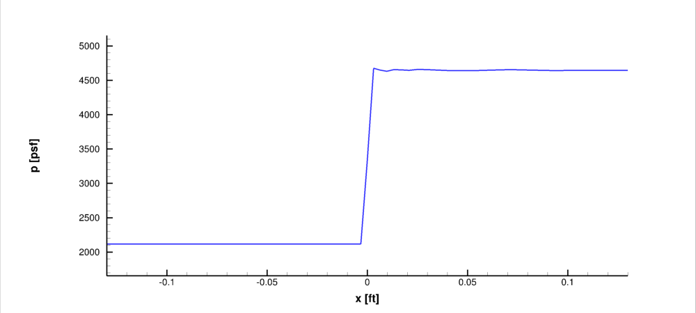
Figure 6. Centerline pressure at the shock
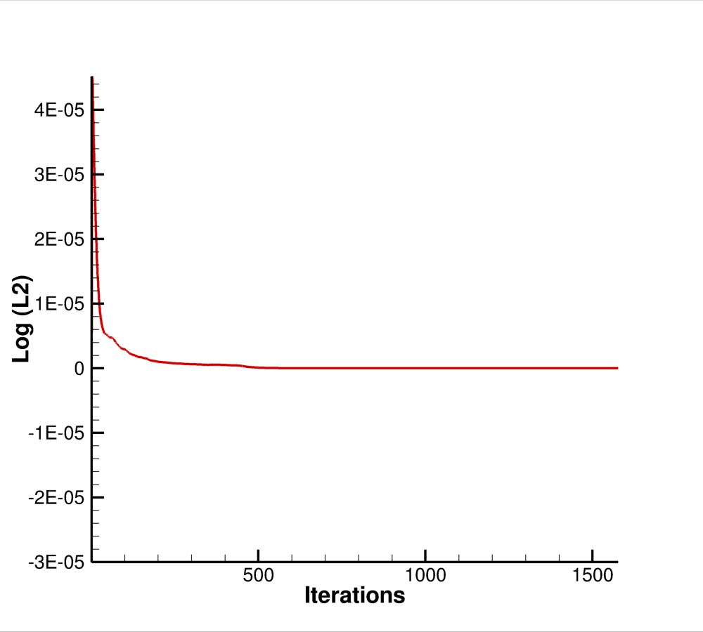
Figure 7. Residual plot used for determining convergence
This validation test case was performed by Keven Lenahan. Contact: Manan Vyas, (216) 433-6053. MS 5-12, NASA Glenn Research Center, 21000 Brook Park Road, Cleveland, Ohio, 44135.