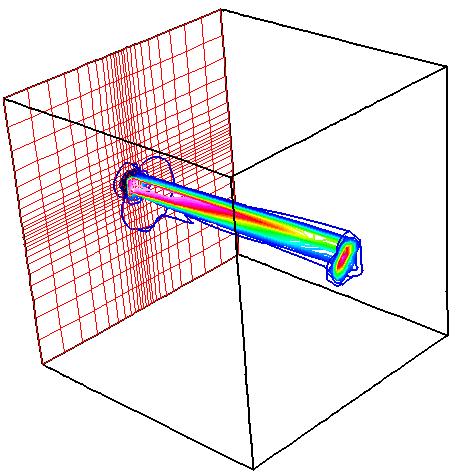
Figure 1. The computational domain, inflow grid, and Mach
contours for a jet injection from a square region on the I1 boundary.
Figure 1. The computational domain, inflow grid, and Mach
contours for a jet injection from a square region on the I1 boundary.
This verification case invovles a square jet injected into a cubical domain. It demonstrates and verifies the application of the ARBITRARY INFLOW boundary condition for holding total pressure, total temperature, and flow angles at an arbitrary inflow boundary.
The computational domain is a cube with sides of 10 inches. The injection region is a square with sides of length 0.5 inches and is centered on the I1 boundary. This region is gridded with 5 evenly-spaced grid points in both directions. Thus the jet inflow region consists of the grid points J11 to J15 and K11 to K15 on the I1 boundary. The grid then stretches gradually away from this region out to the other boundaries. The resulting grid density is 21 x 25 x 25. The common grid file is inject.cgd.
Table 1 lists the boundary condition types used for this case.
| I1 | ARBITRARY INFLOW |
|---|---|
| IMAX | OUTFLOW |
| J1 | INVISCID WALL |
| JMAX | INVISCID WALL |
| K1 | INVISCID WALL |
| KMAX | INVISCID WALL |
The entire I1 boundary is specified as an arbitrary inflow boundary with most of the boundary being a uniform inflow at the freestream conditions with the center square region being defined as a jet in the input data file inject.dat. GMAN is used to set the boundary conditions using the command input file gman.com
gman < gman.com
The freestream flow conditions are specified in Table 2.
| Mach number | Total Pressure (psia) | Total Temperature(R) | Angle-of-Attack (deg) | Angle-of-Sideslip (deg) |
|---|---|---|---|---|
| 0.4 | 10.0 | 300.0 | 0.0 | 0.0 |
The conditions for the I1 boundary of zone 1 is specified using the UNIFORM keyword in the ARBITRARY INFLOW keyword section of the input data file inject.dat to have a uniform inflow at the freestream conditions. Along with this, a square jet is specified using the IJK_RANGE keyword. The uniform jet has the conditions as specified in Table 3.
| Mach number | Total Pressure (psia) | Total Temperature(R) | Angle-of-Attack (deg) | Angle-of-Sideslip (deg) |
|---|---|---|---|---|
| 0.5 | 12.0 | 500.0 | 5.0 | -5.0 |
Six runs are performed corresponding to different jet conditions. These are listed in Table 4. Runs A and B do not have the jet and simply verify that the uniform freestream inflow is maintained when HOLD_CHARACTERISTIC or HOLD_TOTALS, respectively, is used. The HOLD_CHARACTERISTIC imposes the original arbitrary inflow boundary condition in which only the total pressure is held fixed. The HOLD_TOTALS keyword holds the total pressure, total temperature, and flow angles fixed. Runs C and D involve a uniform jet injection at the conditions listed in Table 3 when HOLD_CHARACTERISTIC or HOLD_TOTALS, respectively, is used. Run E uses multiple IJK_RANGE keywords to set spatially varying conditions at the jet inflow. The IJK_RANGE keywords essentially build a "step pyramid" of increasing Mach, pressure, temperature, and flow angles as one proceeds toward the center of the jet injection region. Run F starts with the solution file inject.E.cfl and reads the arbitrary inflow conditions from the respective solution point of the file.
The entire flow domain is initialized by WIND using the freestream flow conditions except at the jet injection region on I1 where the jet conditions are imposed. The IJK_RANGE keyword used to specify the jet injection can be used to initialize more of the domain downstream of the injection region - but that is not done here.
| Run | Description | Input File | List File | Inflow |
|---|---|---|---|---|
| A | No jet. HOLD_CHARACTERISTIC. | inject.A.dat | inject.A.lis | inflow.A.gen |
| B | No jet. HOLD_TOTALS. | inject.B.dat | inject.B.lis | inflow.B.gen |
| C | Uniform Jet. HOLD_CHARACTERISTIC. | inject.C.dat | inject.C.lis | inflow.C.gen |
| D | Uniform Jet. HOLD_TOTALS. | inject.D.dat | inject.D.lis | inflow.D.gen |
| E | Pyramid Jet. HOLD_TOTALS. | inject.E.dat | inject.E.lis | inflow.E.gen |
| F | Inflow from solution. HOLD_TOTALS. | inject.F.dat | inject.F.lis | inflow.F.gen |
The computation is performed using the time-marching capabilities of WIND to approach the steady-state flow starting from the initial conditions generated by WIND.
The input data files for each run of WIND are listed in Table 4. The freestream keyword indicates that the total freestream flow conditions are specified as Mach number, pressure (psia), temperature (R), angle-of-attack (degrees), and angle-of-sideslip (degrees). The turbulence inviscid keyword indicates that viscosity is not modelled. The downstream pressure keyword indicates that the static pressure as obtained from the freestream keyword is imposed at the OUTFLOW boundary (IMAX). The cycles keyword indicates that 200 cycles will be run. The iterations per cycle keyword indicates that 5 iterations will be run for that cycle. The convergence level keyword indicates that the computation will stop if the L2 norm of the solution drops below a value of 1.0E-9. The cfl keyword indicates that a CFL number of 1.0 will be used. By default, WIND uses local maximum allowable time-step based on the specified CFL number. The arbitrary inflow section defines the conditions on the ARBITRARY INFLOW boundary (I1). The uniform keyword sets the default conditions, which are the same as specified in the freestream keyword. The ijk_range keyword then sets the total flow conditions in the specified grid range. The hold_totals keyword indicates that the total temperature and flow angles are to be held fixed along with the total pressure.
The WIND solver is run by entering
wind -runinplace -dat inject
This runs the wind script which sets up the problem for solver. The runinplace option indicates that WIND is to be run in the current directory. The computation creates an output list file inject.lis. The list files for the runs are listed in Table 4.
RESPLT reads the output list file and creates a GENPLOT file nsl2.gen containing the L2 residual to examine the convergence of the computation,
resplt < resplt.nsl2.com
cfpost < cfpost.nsl2.com
where resplt.nsl2.com is the command input file for CFPOST. A GENPLOT file named nsl2.gen is created and plotted using CFPOST. The iterative convergence was demonstrated for each run.
CFPOST is used to create the PLOT3D solution file for visualization.
cfpost < cfpost.plot3d.com
The PLOT3D grid and solution files are named inject.x and inject.q, respectively. They are unformatted, whole, 3D, and multi-zone.
CFPOST can list out the conditions at the jet inflow region to examine whether the total conditions and flow angles were held fixed.
cfpost < cfpost.inflow.com
where cfpost.inflow.com is the command input file for CFPOST. A GENPLOT file named inflow.gen is created. The GENPLOT file lists the Mach number, total pressure, total temperature, local alpha, local beta, u-velocity, v-velocity, w-velocity, and the total velocity at each grid point in the jet inflow region. The GENPLOT files of the inflow conditions for each run are listed in Table 4.
The GENPLOT file of the properties at the inflow (inflow.gen) are examined to determine the performance of the arbitrary inflow boundary condition. Upon examing the inflow conditions for Runs A (inflow.A.gen) and B (inflow.B.gen) one can see that the freestream conditions are maintained on the boundary.
Runs C and D impose a uniform jet. Run C uses HOLD_CHARACTERISTICS. The file inflow.C.gen indicates that total pressure is held fixed; however, total temperature and flow angles are not, which is expected. Run D uses HOLD_TOTALS. The file inflow.D.gen indicates that total pressure, total temperature and flow angles are held fixed. The local angle-of-sideslip used in CFPOST is different than the one used in WIND, and so, the "locbeta" presented in inflow.D.gen are not exactly at -5.0.
Run E imposes the "step pyramid" spatial variation in jet conditions as shown in inject.E.dat. The HOLD_TOTALS is used. The file inflow.E.gen indicates that the total pressure, total temperature and flow angles are held fixed.
Run F starts from the solution file from run E, inflow.E.cfl, and uses the total conditions from each boundary solution points when enforcing the HOLD_TOTALS keyword. The file inflow.F.gen indicates that the total pressure, total temperature and flow angles are held fixed for the pyramid jet imposed in run E.
This file was last updated on October 28, 2002. Questions and comments on this case can be forwarded to
John W. Slater
NASA Glenn Research Center, MS 86-7
21000 Brookpark Road
Brook Park, Ohio 44135
Phone: (216) 433-8513
e-mail: John.W.Slater@grc.nasa.gov