This report documents the WIND k-epsilon model validation results for a two-dimensional ejector nozzle flow. Comparisons are made between the NPARC and WIND k-epsilon model implementations and with the WIND SST model results. In addition, the effects of the Sarkar compressibility correction and the variable C_mu option on the stability and convergence of the WIND k-epsilon model are discussed.
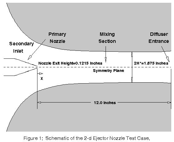
The focus of this investigation was the turbulent flow through a two-dimensional ejector nozzle which was tested by Gilbert and Hill (1973) and is shown schematically in Figure 1. This flow features the turbulent mixing between the primary jet and entrained secondary air as well as the interaction with the wall boundary layers. The rectangular mixing section is formed by the symmetrically contoured upper and lower walls and the two flat sidewalls. The widths of both the primary nozzle discharge slot and the mixing section were 8.00 inches. Other dimensions of the system are shown in Figure 1. Suction slots were placed in the corners of the mixing section to prevent flow separation. The experimental data to be used for comparison purposes consists of velocity and temperature measurements at several axial locations. The inflow conditions used in the numerical computations correspond to those of run 9 in the report by Gilbert and Hill (1973) and are listed in the following table.
| Pressure (psia) | Total Temperature (R) | Mach Number | |
| Secondary Inflow | 14.73 (total) | 550 | 0.2 |
| Primary Nozzle | 35.73 (total) | 644 | 0.07 |
| Downstream | 13.45 (static) | 550 |
| EJTEMP.data |
| EJVELS.data |
All of the archive files of this validation case are available in the Unix compressed tar file eject.tar.Z.
The files can then be accessed by the commandsuncompress eject.tar.Z
tar -xvof eject.tar
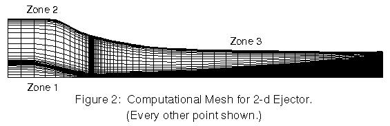
Due to the symmetric nature of the ejector nozzle and mixing section, only half of the ejector was modeled numerically. The 131x121 mesh of Georgiadis, Chitsomboon, and Zhu (1994) was used in these calculations. This single zone mesh was split into three separate zones for use with the WIND code: 1) a 31x41 mesh for the flow inside the primary nozzle, 2) a 31x71 mesh for the secondary inflow region, and 3) a 101x121 mesh within the mixing section. The resultant grid is shown in Figure 2. The grid in PLOT3D format (3D, multi-block, formatted) is eject.x.fmt.
| Common Grid |
| eject.cgd |
| NPARC input data file | nparc2d.inp |
| WIND input data files | wke01.dat |
| wke03.dat | |
| wke04.dat | |
| wke05.dat | |
| wsst.dat |
The basic procedure used in performing this validation is: 1) initialize the flow field to uniform conditions, 2) run for 1000 iterations using the SST turbulence model, 3) initialize the Chien k-epsilon turbulence model from the SST turbulent viscosity and run for 10000 iterations.
All calculations were begun using a CFL number of 1.5. However, at this CFL number several cases diverged, causing the code to stop. Lowering the CFL number to 0.5 for most of these cases seemed to remedy this problem, but required that the solutions be run three times longer to reach the same level of convergence. The following table summarizes these results.
| Case | CFL=1.5 | CFL=0.5 |
| No Corrections | Diverged | No difficulties |
| Sarkar | Diverged | Diverged |
| Var.C_mu | Diverged | No difficulties |
| Var.C_mu+Sarkar | No difficulties |
| Common Solution | List |
| wke01r.cfl | wke01.lis.Z |
| wke03r.cfl | wke03.lis.Z |
| wke04r.cfl | wke04.lis.Z |
| wke05r.cfl | wke05.lis.Z |
| wsst.cfl | wsst.lis.Z |
In most cases, the solution diverged just downstream of the primary nozzle exit where high flow gradients cause the production of turbulent kinetic energy to become quite large. This effect also seems to be aggravated by the zonal interface at the nozzle exit plane. The WIND code combines the half-cell at the boundary of the zone with the first interior cell when computing the cell volume. This makes it difficult to compute derivatives along the zone boundary, because metric terms cannot be recovered. For cases where large flow gradients exist within these first two nodes, values for the derivatives may be inaccurate.
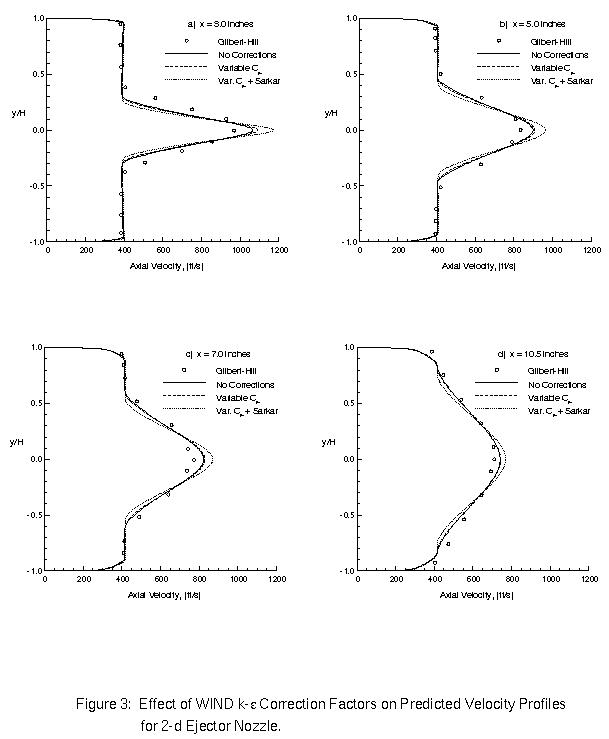
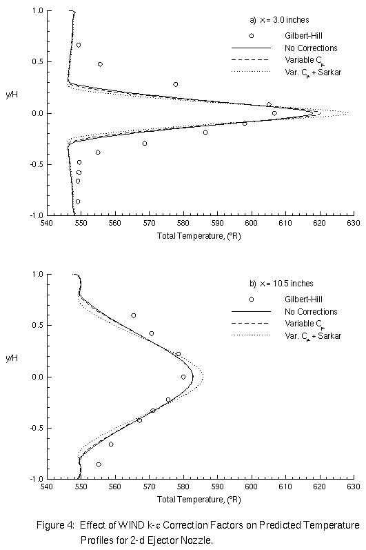
Figures 3 and 4 show the effects of the WIND k-epsilon correction factors on the predicted velocity and temperature profiles. The variable C_mu option has only a minor effect on the centerline velocity at the first axial location. For this particular case, the production of turbulent kinetic energy exceeds the dissipation rate only near the exit of the primary nozzle. Thus the variable C_mu option affects only a small region of the entire computational domain and does not significantly affect the downstream profiles. Use of the Sarkar compressibility correction with the variable C_mu option reduces the decay rate of the jet at all axial locations.
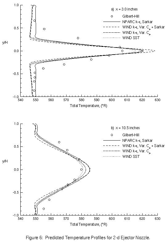
Cross-code comparisons of the velocity and temperature profiles are made in Figures 5 and 6. These results show that all of the models yield similar results with the WIND SST model giving the best overall agreement with the experimental data.
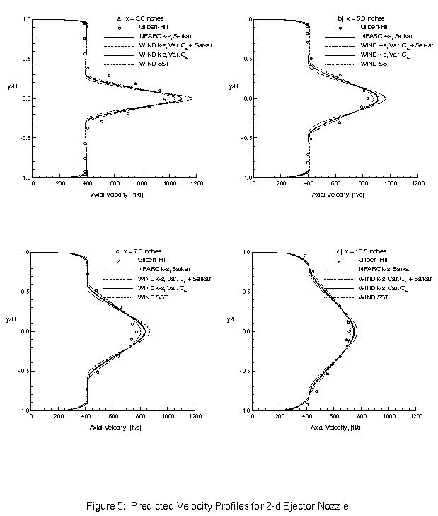
For the case of the 2-d ejector nozzle, the WIND k-epsilon model was found to give results similar to those using the NPARC k-epsilon model. However, the WIND version demonstrated a minor stability problem along the zonal interface at the trailing edge of the primary nozzle. This problem appears to stem from the developing shear layer between the primary and secondary flows and the accompanying high levels of turbulent kinetic energy. The WIND code's use of oversized cells along the zone boundary appears to aggravate this condition.
Fortunately, the variable C_mu option helps to remedy this problem by reducing the turbulent viscosity in regions where the production of turbulent kinetic energy significantly exceeds the rate of dissipation. This option did not appear to affect the downstream profiles considerably. Because of this stabilizing effect and the fact that the variable C_mu option resulted in improved downstream pressure distributions for the Sajben diffuser strong-shock case, it is recommended that this option be made a default setting. For situations where this option is not desired, the user will need to indicate so in the WIND input file.
It is also recommended that the default setting for the compressibility correction be ``none''. While the results for the aforementioned Sajben diffuser case using the Sarkar correction did improve the prediction of the shock position, the results for this ejector problem show that the correction results in a mixing rate that is too slow compared to the data. Making the default setting ``none'' will force the user to decide when this correction is necessary.
The ejector nozzle flowfield was solved on an unstructured grid using the unstructured grid solver in Wind-US 3.139. The objective was to validate the unstructured solver for the ejector nozzle flow. The input and output files and comparisons of the velocity and total temperature profiles can be found on the Unstructured Ejector Nozzle page.
Georgiadis, N.J., Chitsomboon, T., and Zhu, J., ``Modification of the Two-Equation Turbulence Model in NPARC to a Chien Low Reynolds Number k-epsilon Formulation,'' NASA TM-106710, September 1994.
Gilbert, G.B., and Hill, P.G., ``Analysis and Testing of Two-Dimensional Slot Nozzle Ejectors With Variable Area Mixing Sections,'' NASA CR-2251, May 1973. PDF
This validation test case was performed by Dennis Yoder. (216) 433-8716. MS 86-7, NASA Glenn Research Center, 21000 Brook Park Road, Cleveland, Ohio, 44135.