
(a). pexit / pt = 0.89.

(b). pexit / pt = 0.75.

(c). pexit / pt = 0.16.

Figure 1. Mach number contours for Converging-Diverging Verification (CDV) Nozzle.
\

(a). pexit / pt = 0.89.

(b). pexit / pt = 0.75.

(c). pexit / pt = 0.16.

Figure 1. Mach number contours for Converging-Diverging
Verification (CDV) Nozzle.
This study uses the WIND CFD code to simulate the three flows through the CDV nozzle as part of the verification of WIND.
These simulations use a planar, axisymmetric flow domain bounded by the centerline and the nozzle walls. The inflow boundary is at x = 0 inches and the outflow boundary is at x = 10 inches. The throat is at x = 5 inches.
The grids consist a single zone with uniform spacing in the streamwise direction with the potential of clustering near the centerline and nozzle walls in the radial direction. A Fortran program cdnozg.f creates a planar (two-dimensional or axisymmetric) or a three-dimensional grid for the nozzle. At each streamwise grid surface, the coordinates are at a constant-x value. This introduces some non-orthogonality at the nozzle wall; however, it is considered slight. Figure 2 shows a representative grid, which is coarsened for presentation.

Figure 2. Example grid for CDV nozzle generated by cdnozg.
Three grids were generated for these simulations to enable a formal grid convergence study. The information on the grids is presented in Table 1.
| Grid | Dimensions | Wall Spacing | WIND Grid File |
|---|---|---|---|
| A. Coarse | 51 x 31 | 0.01 | run.A.cgd |
| B. Medium | 101 x 61 | 0.005 | run.B.cgd |
| C. Fine | 201 x 121 | 0.0025 | run.C.cgd |
For WIND, the Plot3d grid files generated by cdnozg were converged to the WIND grid file format using CFCNVT.
cfcnvt < cfcnvt.x.com
A Plot3d file (formatted, 2D, single-block) of the fine grid is available as the file grid.C.fmt.
The initial conditions for the CFD simulations are obtained from the total pressure (1.0 psi) and total temperature (100 R) of the plenum with the assumption of an inflow Mach number of 0.2. Flow angles are zero degrees.
The inflow boundary is subsonic with total pressure, total temperature, and flow angles held fixed. The outflow boundary imposes the static pressure for a subsonic outflow. If the outflow is supersonic, then an extrapolation of the flow is imposed. The centerline and nozzle surface is specified as slip walls.
For WIND, the boundary conditions are imposed using GMAN
gman < gman.com
The simulation involved starting from the initial solution and marching in pseudo-time using a local CFL number until a steady-state solution was obtained as determined by the convergence criteria.
For input parameters for the WIND simulations included in the WIND input data files listed in Table 2. Nine simulations were perfored - each grid was simulated with each of the three exit pressures.
Table 2 presents the WIND solution and list files for the nine simulations that were performed. The list files are ASCII files of the run and convergence information. All are compressed files, except for the first one, which allows an example of the WIND output.
| Grid | pexit/pt | Input Data File | Solution File | List File |
|---|---|---|---|---|
| A. Coarse | 0.89 | run.Ap89.dat | run.Ap89.cfl | run.Ap89.lis |
| A. Coarse | 0.75 | run.Ap75.dat | run.Ap75.cfl | run.Ap75.lis.Z |
| A. Coarse | 0.16 | run.Ap16.dat | run.Ap16.cfl | run.Ap16.lis.Z |
| B. Medium | 0.89 | run.Bp89.dat | run.Bp89.cfl | run.Bp89.lis.Z |
| B. Medium | 0.75 | run.Bp75.dat | run.Bp75.cfl | run.Bp75.lis.Z |
| B. Medium | 0.16 | run.Bp16.dat | run.Bp16.cfl | run.Bp16.lis.Z |
| C. Fine | 0.89 | run.Cp89.dat | run.Cp89.cfl | run.Cp89.lis.Z |
| C. Fine | 0.75 | run.Cp75.dat | run.Cp75.cfl | run.Cp75.lis.Z |
| C. Fine | 0.16 | run.Cp16.dat | run.Cp16.cfl | run.Cp16.lis.Z |
Convergence was determined by monitoring the decline of the L2 norm of the residual. A leveling-out of the Log of the L2 norm suggested iterative convergence. Convergence was also determined by monitoring the throat Mach number and recovery and the exit Mach number and recovery until those values no longer significantly changed.
The CFPOST utility available with WIND was used to extract the information from the flow solution.
Plots of the comparison of the Mach numbers and static pressures for the respective exit pressure ratios along the centerline of the nozzle are presented in Figures 3 to 8. Each plot contains the analytic results with results for each grid. In general, the simulations do well, even for the coarse grids. The exception are the Mach numbers downstream of the shock. There was significant variation in the flow downstream of the shock for the exit pressure pexit / pt = 0.75. This can also be seen in Mach contours of Figure 1(b). The cause of this is likely the presence of the normal shock close to the constant pressure subsonic outflow, which is highly reflective in nature.
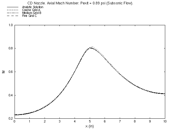
Figure 3. Mach number along the centerline for pexit / pt = 0.89.
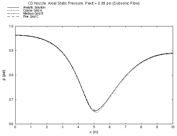
Figure 4. Static pressure along the centerline for pexit / pt = 0.89.
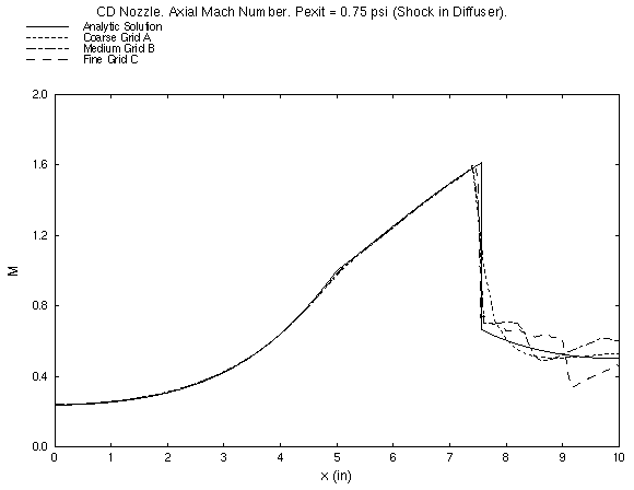
Figure 5. Mach number along the centerline for pexit / pt = 0.75.
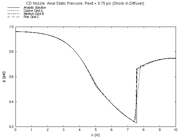
Figure 6. Static pressure along the centerline for pexit / pt = 0.75.
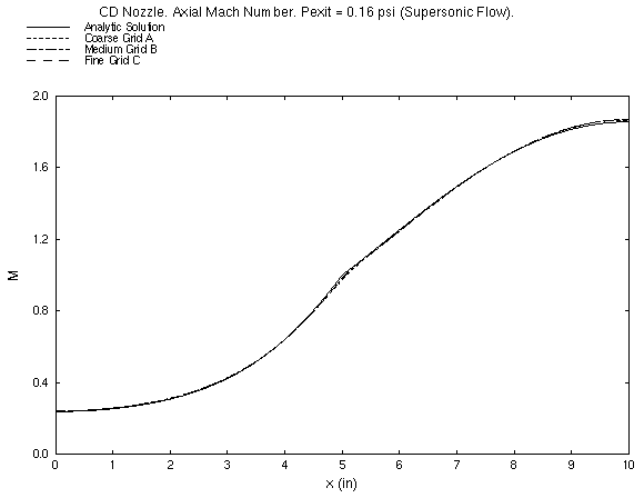
Figure 7. Mach number along the centerline for pexit / pt = 0.16.
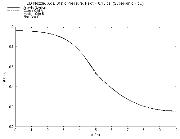
Figure 8. Static pressure along the centerline for pexit / pt = 0.16.
A formal grid convergence study is currently being performed.
The simulations were performed on an Silicon Graphics Octane with 300 MHz R12000 processors. Each simulation used a single processor.
All of the smaller files of this study (all except the grid, solution, and list files) are available in the Unix compressed tar file cdv01.tar.Z. The files can then be accessed by the commands:
uncompress -c cdv01.tar.Z | tar xvof -
This study was created on February 8, 2001 by John W. Slater, who may be contacted at:
NASA Glenn Research Center, MS 86-7
21000 Brookpark Road
Cleveland, Ohio 44135
Phone: (216) 433-8513
e-mail: John.W.Slater@grc.nasa.gov