|
|
The Wandering Wind Tunnel
Abstract:
The Wandering
Wind Tunnel is a complete stand alone, sub scale wind tunnel that is small
enough to be transported on the back of a pick-up truck and large enough
for meaningful data. Six students from Barberton High School were selected
to work at NASA Lewis Research Center in Cleveland, Ohio for five weeks
during the summer of 1994 to begin a research project that would lead
them to both a practical and accurate design. They were then to build
the small portable wind tunnel when returning to Barberton High School.
The wind tunnel, when complete, will eventually travel around to area
high schools for aerospace testing. It is hoped that it will be a catalyst
for the application of computational fluid dynamics in the high schools
and also provide valid data that can be electronically transferred while
networking to other remote science classrooms. Educational Paper for Supercomputing
1995 The Wandering Wind Tunnel Project A project for the design and construction
of a subsonic, small-scaled wind tunnel to be used to explain aerospace
engineering fundamentals to pre-college students; the completed wind tunnel
will be portable and will travel to Northern Ohio high school sites for
data acquisition throughout the school year.
Student
Authors:
Todd Buxton
Todd Fleet
Davelene Israel
Jeffrey Heilman
Joshua Humphrey
James Mongiardo
Barberton
High School 489 Hopocan Avenue Barberton, OH 44203 216-753-1084 fax 216-848-5517
January
30, 1995 Presenting Author: Carol Hodanbosi Physics Instructor Barberton
High School 489 Hopocan Avenue Barberton, OH 44203 216-753-1084 fax 216-848-5517
1.0
Introduction
2.0 Design Team
3.0 Wind Sections
3.1 Test Section
3.2 Contraction Cone
3.3 Settling Chamber
3.4 Diffuser and Fan Housing
4.0 Data Acquistion
5.0 Safety Features
6.0 Cost
7.0 Conclusion
1.0
Introduction
The Wandering Wind Tunnel Project was initiated to provide a way for high
school students to learn about aerodynamics and computational fluid dynamics
through experimentation on a portable wind tunnel. The wind tunnel itself
was designed to be a complete, stand-alone, sub-scale subsonic project;
small enough to be transported on the back of a pick-up truck, but large
enough for the production of meaningful data. The wind tunnel will provide
data to the various Ohio high schools involved in the HPCC (High Performance
Computing and Communications) K-12 pilot project, a program designed to
bring technology into the science and mathematics classroom environment.
The data collected will be analyzed on high performance computers funded
by HPCC, and will provide an opportunity for data transfer among the schools
through an electronic network.
2.0
The Design Team
The design team, which planned and constructed the wind tunnel, consisted
of six students from Barberton High School. The students initially involved
in the project were: Todd Buxton, senior; Todd Fleet, sophomore; Nicholas
Grinder, sophomore; Jeff Heilman, junior; Josh Humphrey, junior; and Davelene
Israel, junior. James Mongiardo, a junior, also became involved with the
project at a later date, when Nicholas Grinder moved to another school.
These students were previously involved in a Supercomputing Program with
Carol Hodanbosi, physics teacher at Barberton High School. The Supercomputing
Program was also funded by HPCC and NASA Lewis Research Center as part
of a K-12 pilot program. The project mentor was Dr. Colin Drummond, an
aerospace research engineer at NASA Lewis Research Center, in Cleveland,
Ohio. Funding for the project came from AIAA, (American Institute of Aeronautics
and Astronautics), the northeastern Ohio branch, the NASA Lewis Research
Center in Cleveland, Ohio, in conjunction with the HPCC K-12 pilot program,
and OAI (Ohio Aerospace Institute).
3.0
The Wind Tunnel Components
The wind tunnel is comprised of five main parts, listed in order from
front to back: the settling chamber, the contraction cone, the test bed,
the diffuser, and the fan housing with a variable speed motor. Also included
will be an IBM 486SX computer, suitable software for air flow analysis,
an A/D converter, a multiplexer, thermocouples, temperature and pressure
probes, and a force balance model mount.
3.1
Test Section
The deciding factor for almost every component of the wind tunnel was
the size of the test bed, which, in turn, is determined by the size of
the object to be tested. The test bed is shown in figure 1.
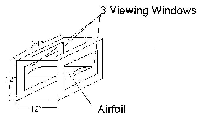 The entire
wind tunnel had to be small enough to fit inside the bed of a pick-up
truck while being transported. Based on this restriction, the test section
was designed as 1' x 1' x 2'. The test section was made of 1 1/2" angle
irons, and has three acrylic viewing windows. Each end of the test bed
has 1 1/2" metal angle flanges to bolt to the other sections. The flanges
allows for easy disassembly, another requirement for the portability of
the wind tunnel.
The entire
wind tunnel had to be small enough to fit inside the bed of a pick-up
truck while being transported. Based on this restriction, the test section
was designed as 1' x 1' x 2'. The test section was made of 1 1/2" angle
irons, and has three acrylic viewing windows. Each end of the test bed
has 1 1/2" metal angle flanges to bolt to the other sections. The flanges
allows for easy disassembly, another requirement for the portability of
the wind tunnel.
3.2
The Contraction Cone
The second section of the wind tunnel designed was the contraction cone
(figure 2), which proved to be the most difficult section as far as design
and materials.
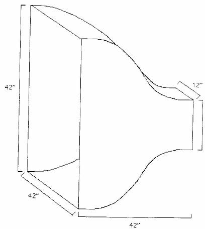 The contraction cone's purpose is to take a large volume
of low velocity air and reduce it to a small volume of high velocity air
without creating turbulence. The size of the large end, nearest the settling
chamber was set at 3.5' x 3.5'. Many of the ratios the design team used
were selected with the guidance of the book "Low-Speed Wind Tunnel Testing"
by William Rae, Jr and Alan Pope. The small end of the contraction cone
was set at 1' x 1' to fit directly onto the test section. The shape of
the contraction cone was a cubic curve, modeled after larger wind tunnels.
The contraction cone originally was designed to be made out of fiberglass,
but due to difficulties involved with heating and molding it, it was decided
by the group to be made out of 14 gauge sheet metal instead. The sheet
metal also has metal flanges on each side to bolt together with the other
sections.
The contraction cone's purpose is to take a large volume
of low velocity air and reduce it to a small volume of high velocity air
without creating turbulence. The size of the large end, nearest the settling
chamber was set at 3.5' x 3.5'. Many of the ratios the design team used
were selected with the guidance of the book "Low-Speed Wind Tunnel Testing"
by William Rae, Jr and Alan Pope. The small end of the contraction cone
was set at 1' x 1' to fit directly onto the test section. The shape of
the contraction cone was a cubic curve, modeled after larger wind tunnels.
The contraction cone originally was designed to be made out of fiberglass,
but due to difficulties involved with heating and molding it, it was decided
by the group to be made out of 14 gauge sheet metal instead. The sheet
metal also has metal flanges on each side to bolt together with the other
sections.
3.3
The Settling Chamber
The settling chamber was designed after the contraction cone. This section
is the front section of the wind tunnel and is placed onto the contraction
cone (figure 3).
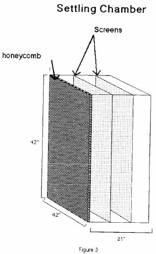 The purpose of the settling chamber is to `straighten'
the air flow as the wind tunnel draws air in from the surrounding air,
channeling the ambient air. The settling chamber's cross section dimensions
are 3.5' x 3.5', and match up with the dimensions of the contraction cone.
It will be made out of 1/2" plywood and will have 1 1/2" angle irons as
a flange to bolt it to the contraction cone. Its length is 21" to accommodate
three different flow straightening devices. The first of the flow straightening
devices is the honeycomb (figure 3). The honeycomb is a series of tubes
laid lengthwise in the air stream. Its purpose is to allow the air to
only enter in one direction, parallel to the airflow of the tunnel so
that cross-flow velocities will not cause swirling winds in the tunnel.
The design team decided upon 1/8" diameter straws cut into 1" pieces for
their honeycomb. The straws will be placed at the very front of the settling
chamber, aligned parallel to the air flow and held in place by double-sided
masking tape. The second and third flow-straightening devices are screens
(figure 3). Their purpose is to make the velocities of the wind in the
wind tunnel equal by eliminating fast and slow air velocities. As the
air passes through the screens, the resulting drop in pressure across
the screen creates constant air speed in the tunnel. The two screens will
be approximately 6" apart from each other and will be placed 6" behind
the honeycomb. All three of the flow straighteners will be removable for
easy cleaning and maintenance.
The purpose of the settling chamber is to `straighten'
the air flow as the wind tunnel draws air in from the surrounding air,
channeling the ambient air. The settling chamber's cross section dimensions
are 3.5' x 3.5', and match up with the dimensions of the contraction cone.
It will be made out of 1/2" plywood and will have 1 1/2" angle irons as
a flange to bolt it to the contraction cone. Its length is 21" to accommodate
three different flow straightening devices. The first of the flow straightening
devices is the honeycomb (figure 3). The honeycomb is a series of tubes
laid lengthwise in the air stream. Its purpose is to allow the air to
only enter in one direction, parallel to the airflow of the tunnel so
that cross-flow velocities will not cause swirling winds in the tunnel.
The design team decided upon 1/8" diameter straws cut into 1" pieces for
their honeycomb. The straws will be placed at the very front of the settling
chamber, aligned parallel to the air flow and held in place by double-sided
masking tape. The second and third flow-straightening devices are screens
(figure 3). Their purpose is to make the velocities of the wind in the
wind tunnel equal by eliminating fast and slow air velocities. As the
air passes through the screens, the resulting drop in pressure across
the screen creates constant air speed in the tunnel. The two screens will
be approximately 6" apart from each other and will be placed 6" behind
the honeycomb. All three of the flow straighteners will be removable for
easy cleaning and maintenance.
3.4
The Diffuser and Fan Housing
The diffuser section (figure 4) of the wind tunnel is necessary to reduce
any air turbulence that could lead back into the test section.
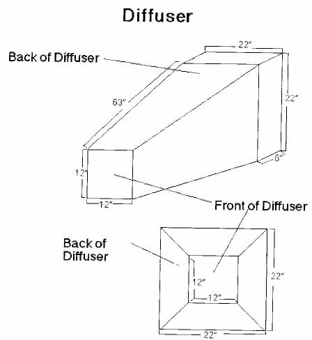 The angle
of the diffuser is based on a ratio of surface area of the end of the
diffuser to the surface area of the front of the diffuser. The dimensions
of the front opening are 12" x 12" and the dimensions of the end opening
are 22" x 22". This gives a ratio of 3.36 to 1. Using this ratio, the
angle of the diffuser was set at 4.8 degrees. The diffuser is 63" long
and will connect to the test section with flanges similar to the ones
used to join the test section and the contraction cone. Following the
diffuser is a fan housing (figure 5) to hold a four blade fan controlled
by a variable speed motor.
The angle
of the diffuser is based on a ratio of surface area of the end of the
diffuser to the surface area of the front of the diffuser. The dimensions
of the front opening are 12" x 12" and the dimensions of the end opening
are 22" x 22". This gives a ratio of 3.36 to 1. Using this ratio, the
angle of the diffuser was set at 4.8 degrees. The diffuser is 63" long
and will connect to the test section with flanges similar to the ones
used to join the test section and the contraction cone. Following the
diffuser is a fan housing (figure 5) to hold a four blade fan controlled
by a variable speed motor.
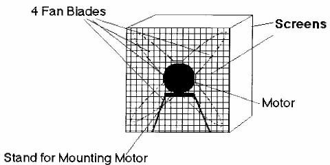
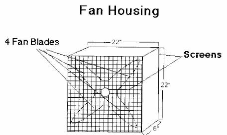 The fan housing will be 25" x 25" wide and
6" in length. The fan will have two screens, one in front and one in back,
for safety purposes. The motor will be mounted on a stand with rubber
pads (figure 6) to reduce the amount of vibration on the wind tunnel.
The fan housing will be 25" x 25" wide and
6" in length. The fan will have two screens, one in front and one in back,
for safety purposes. The motor will be mounted on a stand with rubber
pads (figure 6) to reduce the amount of vibration on the wind tunnel.
4.0
The Data Acquisition System
The main types of test data in any wind tunnel are lift and drag. The
design team used a sting and thrust balance system to measure the effects
of lift and drag on their models. Lift and drag are measured by using
a series of springs, a pivot, and a strain gauge, which are all part of
the thrust balance system. When the air passes over the model, the pivots
and springs create a tighter or looser strain on the gauge. Strain gauge
sensors electrically respond to the change and to its intensities, and
send an voltage change to the A/D board. The A/D board converts the electric
signal into a digital computer language. The computer collecting the data
will be an IBM 486SX, with sixteen input channels. Total and static pressure
readings will be another important source of data. This data provides
a way to find the true air velocity in the tunnel. The wind tunnel will
have four pitot tubes, which will be able to measure static pressure and
total pressure. By substituting in appropriate pressure-velocity equations,
one can determine the velocity from the two pressures. true air speed
= square root of ((2 x dynamic pressure) / air density) dynamic pressure
is measured in pounds / square foot air density is measured in slugs /
cubic foot Flow patterns are the most easily viewed test. The design team
plan on using smoke, tufts, and paint to visualize flow patterns in the
wind tunnel. Smoke will be used to show turbulence around the model. Paint
and tufts will be the least expensive and most effective way to illustrate
flow on the surface. Air foils of various designs will be used in the
wind tunnel. Student projects in science and physics classes could design
airfoils from various airplanes. Additional experiments such as dimpled
versus non-dimpled golf balls and small models of automobiles and downhill
skiers have been considered. The sting, which is the support for the models,
will be adaptable to almost any model. Proper placement of the sting and
model in the test bed will be essential to quality data collection. In
addition to the sting placement, there are also proper component placements.
The pressure rakes, pitot tubes, thermocouples, and thermometer probes
must be placed in way to avoid disturbing the air flow. An analog to digital
(A/D) sixteen channel, 100 kHz converter board, a terminal connector,
and a multiplexer are necessary in the data collection process. Appropriate
flow analysis software will be selected that is simple to operate, has
a large range of functions, and that also has graphic display capabilities.
The five important measurements that need to be found in the low speed
wind tunnel are dynamic pressure, static pressure, total pressure, temperature
and turbulence. Thermocouples, temperature probes, pressure rakes, pitot
tubes and a force balance on the mounting sting are required for the wind
tunnel to generate accurate data.
5.0
Safety Features
Since this machinery will involve the active participation of high school
students, safety is an important factor. To ensure the safety of the individuals
operating the wind tunnel there will be screens located in front of and
behind the fan. This feature will not only protect the operator, but will
also keep the test model from being destroyed by the fan if it slides
from its mounting and out of the test section. Protective caps will be
placed on the front of the settling chamber and the back of the motor
during transportation and periods of low use will lower the amount of
dust build up. A keyed switch will be on the wind tunnel motor so that
it cannot be operated without supervision. Another very important feature
of the wind tunnel is the emergency stop wire. This wire will run along
the outsides of the tunnel and in cases of emergency it can be pulled.
The stop wire will be attached to a shut off switch to automatically stop
the fan.
6.0
Cost
The cost restrictions imposed on the design team involved only the actual
wind tunnel materials, along with the motor and fan. The cost of the computer,
software, A/D board and probes were itemized separately. The design team
initially had a budget of $500.00. They found that with a single speed,
A.C., 1 horsepower motor they would remain inside the budgetary guidelines,
but their experiments would be limited to a single setting. Although the
cost of a variable speed motor, D.C. motor was considerably more, as shown
below, it would provide more flexibility in their experimental data: Variable
Speed Non-variable Speed motor $320 motor $220 controller $370 ______
_____ total $690 $220 The design team decided that the variable speed
motor was well worth the extra expense. The following list shows the cost
of the rest of the materials that were needed for the structure of the
wind tunnel. The contraction cone was contracted out to a local machinist,
so the price listed includes both labor and materials. The straws used
in the settling chamber were donated by a straw manufacturer. Each plastic
straw was 7 3/4 inches in length and one-eighth inch diameter. They were
cut into one inch lengths, using a machine that one of the students made
with the assistance of his father. The design team estimated that they
needed more than 16,000 straws for the settling chamber. The wiring was
required for both the key and selector switch to the motor. The students
completed this wiring by themselves. fan $ 60 wood $180 acrylic glass
$ 30 contraction cone $180 angle irons $ 30 wiring $300 tape $ 20 straws
$ 90 ____________________ total $890 + motor+ controller = $1580
7.0
Conclusion
The wind tunnel project was and will continue to be a learning experience
for all the participants. During this project, the design team learned
that responsibility and teamwork was important for the wind tunnel to
be properly designed and built. At first, it was difficult for the six
high school students to learn to compromise. Each had their own ideas
and had to learn to listen to other opinions that had equal merit. Eventually,
however, they learned to value each member's contribution and worked together
well. Another important aspect of this project was the contribution of
expertise of several of the students' parents. The summer internship gave
each of the students invaluable real world experiences that included;
economics, time constraints, size and weight restrictions on the design
itself, cooperative interaction,interrogation of researchers for important
information, and finally, after all the research was done, critical decision-making.
At this time, the wind tunnel is nearly complete. The design team has
finished most of the important sections, with only one section remaining.
The metal shop class has recently made the motor stand and mount from
the team's specifications. The A/D apparatus, pressure and temperature
probes have been installed and work correctly.The team has to find a way
to reverse the direction of the fan blades (it was designed to exhale
not inhale) and still attach to the motor. A new metal sleeve must be
made for the attachment of the blades to the motor. Plans for the 1995-96
year will include the following projects: Physical science and physics
classes, along with two fourth grade classes will work cooperatively to
develop experiments for the wind tunnel. Together they will test existing
objects that they may choose, such as golf balls and model cars and planes.
They will also design shapes from modeling clay to be placed in the test
bed. Sensors located in the test section are connected to a computer,
whose software is designed to analyze various air flow patterns. The students
will use the data derived from these experiments to predict how other
objects will behave in the wind tunnel. They will research how air temperature,
air density, humidity, air speed, and the geometry of the objects affect
the air flow. Based on the results of the experiments, they will make
generalizations about good aerodynamic design. The data that they derive
from this activity can be sent via the internet to other schools interested
in acquiring flow data. After Barberton High School has completed its
tests, the wind tunnel will 'wander' to other sites for further experimentation.
The wind tunnel hopefully will become a catalyst for creativity, with
each school creating their own models and experiments for data acquistion.
Bibliography
Rae Jr., William H. and Pope, Alan. Low-Speed Wind Tunnel Testing. New
York,Wiley & Sons, 1984, pages 37-119,126-141,153-183.
Navigation ..

- Beginner's Guide Home Page
|