To move an airplane through the air,
thrust is generated by some kind of
propulsion system.
Beginning with the Wright brothers'
first flight,
many airplanes have used
internal combustion engines
to turn
propellers
to generate thrust.
Today, most general aviation or private airplanes are
powered by internal combustion (IC) engines, much like
the engine in your family automobile.
When discussing engines, we must consider both the
mechanical operation of the
machine and the
thermodynamic
processes that enable the machine to produce useful
work.
On this page we consider the thermodynamics of a
four-stroke
IC engine.
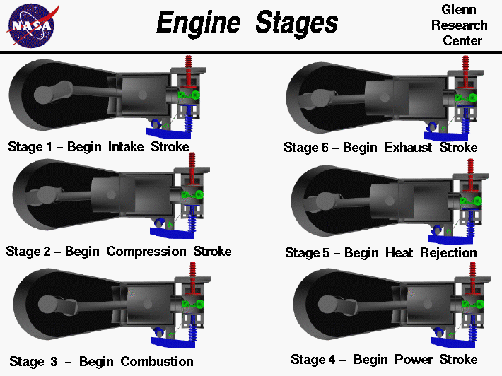
On the figure we show an internal view of the
Wright brothers' 1903 engine at six times, or stages,
during a
thermodynamic cycle.
The Wright engine has been chosen because of its simplicity, but
the same six stages occur in all four-stroke IC engines.
The stages proceed from the upper left to the bottom left, then from
the bottom right to the upper right in a continuous cycle.
We label the stages for the same reasons that we labeled the
stations
of a
gas turbine engine;
to better organize our
analysis
of the performance of the engine.
The thermodynamic cycle for the four-stroke IC engine was developed
by Dr. N. A. Otto, in 1876. The cycle proceeds as follows:
-
The cycle begins when the intake valve opens and a mixture of fuel
and air is drawn into the cylinder from the
intake manifold.
The piston is pulled towards the crankshaft, to the left in the figure,
at constant pressure because the valve is open. The motion of the
piston is called a stroke. Stage 1 is the beginning of the
intake stroke.
-
At the end of the intake stroke, the intake valve is closed and the piston is
moved back towards the combustion chamber.
Since the valves are closed, the pressure and temperature
are increased by the
adiabatic compression.
Stage 2 is the beginning of the
compression stroke.
-
At the end of the compression stroke,
the pressure in the combustion chamber is a maximum.
The spark plug in a modern engine, or the
contact switch
of the Wright engine, then generates an electric spark which ignites
the fuel-air mixture. Stage 3 is the beginning of the
combustion process.
-
Combustion occurs very quickly in an IC engine and occurs at constant
volume
in the combustion chamber. The high pressure forces the piston back
towards the crankshaft. Stage 4 is the beginning of the
power stroke.
-
At the end of the power stroke,
heat
is rejected to the surroundings as required by the
second law
of thermodynamics. Stage 5 is the beginning of the
heat rejection.
-
Following heat rejection, the exhaust valve is opened and the residual
gas is forced out into the surroundings to prepare for the next
intake stroke. Stage 6 is the beginning of the
exhaust stroke.
At the end of the exhaust stroke the conditions have returned to Stage 1
conditions and the cycle repeats itself. The variation of
pressure, and cylinder
volume
can be displayed on a
p-V diagram
for the
Otto Cycle.
The area enclosed by the plot is equal to the useful
work
generated by one cylinder of the engine.
Activities:
Guided Tours
Navigation ..


- Beginner's Guide Home Page
|