As described on the
operation slide,
the Wright brothers'
drag balance
would deflect in the
wind tunnel
when the wind was turned on. The brothers would record the
amount of the deflection on a dial. With this information
they could determine the
drag to lift ratio
of their model.
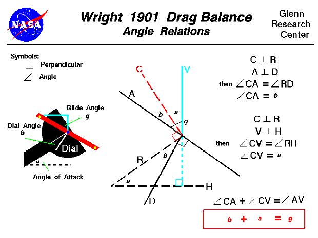
There are three angles involved in the operation of the
drag balance and they are related to each other as we will show
on this page. The angles are: the
angle of attack a of the model, the
dial angle b on the drag balance, and the
glide angle g which is the deflection of the
support arm of the balance from the vertical in the figure.
To determine the relation between the angles we need a theorem from
Euclidian geometry
which deals with angles.
If two angles have their sides mutually perpendicular, the angles are equal.
On the left of the figure we show the configuration of the drag balance with the
three angles noted. In the center of the figure, we show a diagram of the angles
and we have labeled the various lines which form the angles. The arm is labeled
A, a black line falling from left to right. The dial is labeled D, and the reference line for the dial (the line where angle b = 0) is
labeled R. The local vertical is V and the local horizontal is
H. V and H are perpendicular to each other, and the dial
is constructed such that D and A are perpendicular to each other.
We have a construction line, labeled C in red, which is perpendicular
to R. We will describe the angles formed by these lines by two letter
combinations preceded by the symbol {. So the angle formed by line A
and line C will be given by the symbol {AC.
During the operation of the drag balance, we set the angle of attack a
a = {RH
and we measure the angle b.
b = {RD
The glide angle g is the deflection of the arm from the vertical.
g = {AV
Now let's use the geometry theorem to find the angles which the construction line
C makes with the vertical V and the arm A. We will use the
symbol | to denote perpendicular. We made C perpendicular to R
and the arm A is perpendicular to the dial D:
C|R and A|D
Then from the theorem:
{CA = {RD = b
And we know that V is perpendicular to H:
C|R and V|H
Then from the theorem:
{CV = {RH = a
Now if we add the angles {CV and {CA we get:
{CV + {CA = {AV
Substituting the values:
a + b = g
The sum of the dial angle and the angle of attack is equal to the glide angle.
Navigation..


- Beginner's Guide Home Page
|
