|
Engine Power Train
|
Glenn
Research
Center
|

For the forty years following the
first flight
of the Wright brothers, airplanes used
internal combustion engines
to turn
propellers
to generate
thrust.
Today, most general aviation or private airplanes are still
powered by propellers and internal combustion engines, much like your
automobile engine.
We will discuss the fundamentals of the
internal combustion engine using the
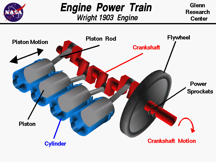
Wright brothers' 1903 engine, shown in the figure, as an example.
The brothers' design is very simple by today's standards, so it is a good
engine for students to study and learn the
fundamentals of engines
and their
operation.
On this page we present a
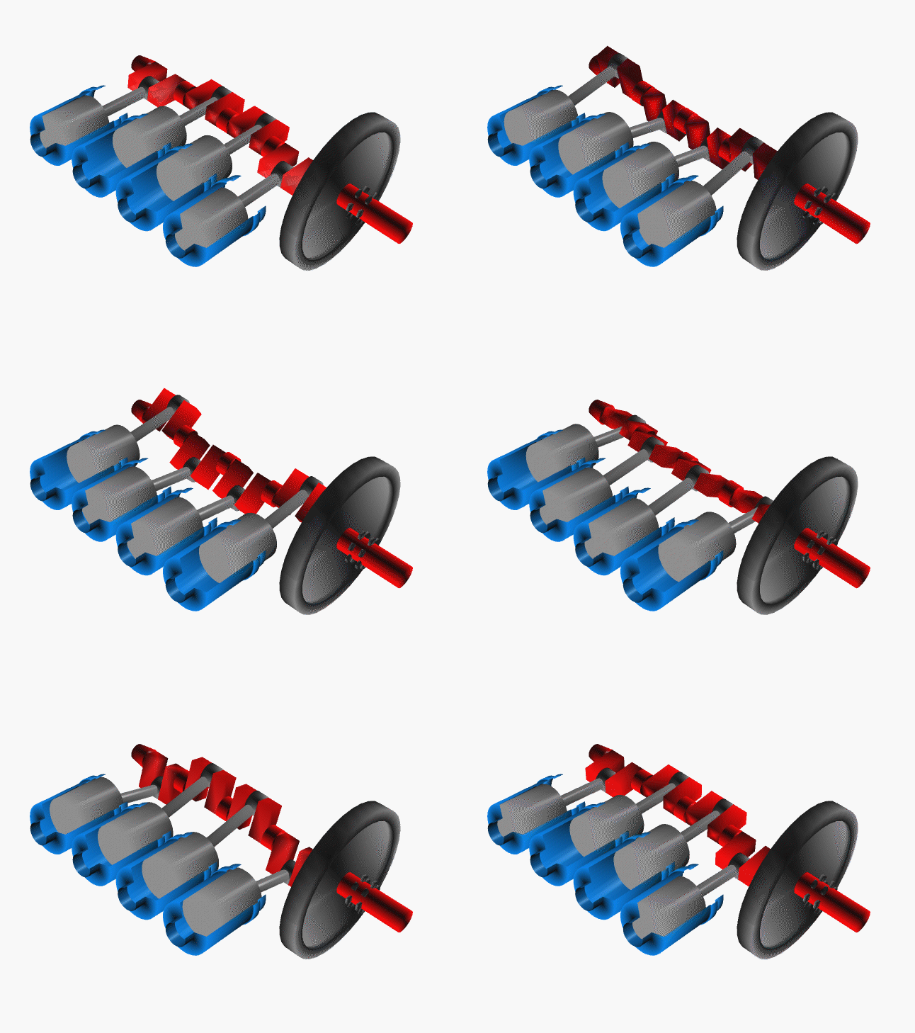
computer animation of the power train of the Wright
brothers' 1903 aircraft engine.
In this animation, and on the figure below,
we have stripped away all of the
engine parts
except those associated with the power train.
The view is from above the rear of the engine.
As the name implies, the job of the power train is to provide the power
to turn the aircraft propellers.
For the brothers' propulsion system, two power sprockets are
located on a rotating crankshaft, colored red, which turns
large "bicycle" chains to power the propellers.
The energy to rotate the crankshaft is provided during the
power stroke
of four pistons, colored gray, moving in enclosed cylinders, colored blue.
The power train converts the linear motion of the pistons
into rotational motion of the crankshaft.
There are three main parts to the power train; the crankshaft,
the pistons, and the cylinders.

The crankshaft is a single, long piece of metal which
is cut into a very specific "snake" shape. The ends of the shaft are rounded
to accept the flywheel and the sprockets at the right of the figure, and
the
timing sprocket on the left end.
The three rounded sections in the middle of the crankshaft ride on bearings in the
crankcase of the engine.
There are four additional rounded sections of the crankshaft which are enclosed
by the ends of the piston rods.
The piston rods are connected to the pistons by pins which you can't see
in this view.
Four
combustion chambers
are connected to the opened ends of the cylinders, to the
left in the figure. During the
combustion
of the fuel, the pressure is increased in the combustion chamber and in the volume formed
by the piston head and the top of the cylinder. The pressure on the head of the
cylinder
generates the force to move the piston and the crankshaft. The pistons fire one
at a
time in a
specified order.
The job of the flywheel is to store the energy from the individual firings so that
the engine runs more smoothly.
Activities:
Guided Tours
Navigation..


- Beginner's Guide Home Page
|
