The propulsion system of an aircraft must
perform two important roles:
- During cruise, the engine must
provide enough thrust, to balance the
aircraft drag while using as little
fuel as possible.
- During takeoff and maneuvers, the
engine must provide
excess thrust to accelerate the
aircraft.
Most modern passenger and military aircraft are powered by
gas turbine engines, which are also called
jet engines. There are several different types
of jet engines, but all jet engines have some parts
in common.
All jet engines have a combustor or
burner in which the air and fuel are mixed and burned.
The
thermodynamics
of the burner play a large role in both the generation of thrust and
in the determination of the fuel flow rate for the engine.
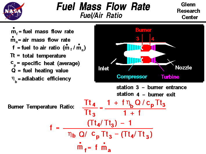
On this page we show the thermodynamic equations which relate the
the temperature ratio in the burner to the fuel mass flow rate.
The fuel mass flow rate mdot f is given in
units of mass per time (kg/sec). The fuel mass flow rate is related to
the total engine
air flow rate mdot a by the fuel to air
ratio
f. The
energy equation
for the burner can be
solved
for the temperature ratio across the burner:
Tt4 / Tt3 = (1 + f * nb * Q / (cp * Tt3)) / (1 + f)
where Tt4 is the burner exit temperature, Tt3 is the burner entrance
temperature, Q is the fuel heating value, cp is the
specific heat coefficient
of air at constant pressure and nb is an efficiency factor
to account for losses in the burner.
Using the temperature equation, and a little algebra,
it is possible to solve for the
fuel to air ratio f. From the fuel to air ratio, we can obtain the
fuel mass flow rate by a simple multiplication.
f = [(Tt4 / Tt3) - 1] / [(nb * Q) / (cp * Tt3) - Tt4 / Tt3]
mdot f = f * mdot a
The engine air flow rate is normally set by
conditions
in the nozzle.
We can use the value of fuel to
air ratio to determine the engine's specific fuel
consumption. As explained in another section of the Beginner's
Guide, the specific fuel consumption and the aircraft
fuel load determine the maximum flight time
and the maximum range of an aircraft.
It would appear that we can make the temperature ratio and resulting thrust
as large as we want
by just increasing the fuel flow rate and the fuel/air ratio. However, the
details of the combustion process sets some limits on values of the fuel/air
ratio. And in engine operation, there is a
maximum burner exit temperature Tt4 which is determined by
materials limits.
If we try to run the engine hotter than this
maximum temperature, the burner and the turbine will be damaged.
You can now use
EngineSim
to study the effects
of different materials on engine operation.
Activities:


Guided Tours
-
 EngineSim - Engine Simulator:

-
 Calculating Fuel Flow Rate:

Navigation ..

- Beginner's Guide Home Page
|
