For the forty years following the
first flight
of the Wright brothers, airplanes used
internal combustion engines
to turn
propellers
to generate
thrust.
Today, most general aviation or private airplanes are still
powered by propellers and internal combustion engines, much like your
automobile engine.
On this page we will discuss the fundamentals of the
internal combustion engine using the
Wright brothers' 1903 engine, shown in the figure, as an example.
The brothers' design is very simple by today's standards, so it is a good
engine for students to study to learn the fundamentals of
engine operation. This type of
internal combustion engine
is called a
four-stroke
engine because there are four movements
(strokes)
of the piston before the entire engine firing sequence is repeated.
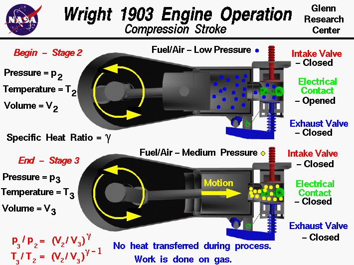
In the figure, we have colored the
fuel/air intake system
red, the
electrical system
green, and the
exhaust system
blue. We also represent the fuel/air mixture and the exhaust gases by small
colored balls to show how these gases move through the engine.
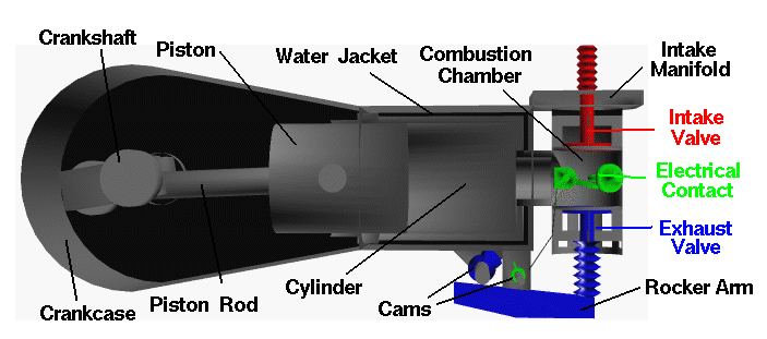
Since we will be referring to the movement of various engine parts, here is
a figure showing the names of the parts:

Mechanical Operation
At the end of the
intake stroke
the fuel/air mixture has been drawn into the cylinder at low (nearly
atmospheric) pressure by the motion of the piston towards the crankshaft
at the left. From our considerations of the
engine cycle,
we designate this condition as
Stage 2
of the Otto cycle.
The intake valve is then closed and the piston begins to
move back towards the combustion chamber at the right.
With both valves closed, the combination of the cylinder and combustion chamber
form a completely closed vessel containing the fuel/air mixture. As the piston
is pushed to the right, the volume is reduced and the fuel/air mixture is
compressed. When the piston has moved completely to the right, we designate
the conditions as Stage 3 of the cycle.
During the compression stroke, the electrical contact is kept opened.
When the volume is the smallest,
and the pressure the highest, the contact is closed and current
flows through the completed circuit.
The switch is then quickly opened, producing a spark
which
ignites the mixture.
Thermodynamics
During the compression, no
heat
is transferred to the fuel/air mixture.
As the volume is decreased because of the piston's motion,
the pressure in the gas is increased.
In the figure, the mixture has been colored blue at stage 2 and
yellow at stage 3 to denote a moderate increase in pressure.
To produce the increased pressure, we have to do
work
on the mixture, just
as you have to do work to inflate a bicycle tire using a pump.
There are thermodynamic
equations
which relate the pressure increase and temperature increase to the
change in volume:
p3 / p2 = (V2 / V3) ^ gamma
T3 / T2 = (V2 / V3) ^ (gamma - 1)
where p is the pressure, T is the temperature,
V is the volume of the mixture,
and gamma is the ratio of
specific heats of the mixture.
The numbers indicate the two stages of the cycle.
Since V2 is greater than V3 and gamma is greater than 1 (1.4 for pure air),
p3 is greater than p2 and T3 is greater than T2. Pressure and temperature
of the fuel/air mixture both increase during the compression process, and
the final value (p3 and T3) depends only on a geometric compression ratio
(V2/V3) to some power multiplied by the intial value (p2 and T2).
Activities:
Guided Tours
Navigation..


- Beginner's Guide Home Page
|
