 |
|
Glenn
|

 |
|
Glenn
|

Most modern passenger and military aircraft are powered by gas turbine engines, which are also called jet engines. The first and most simple type of gas turbine is the turbojet.
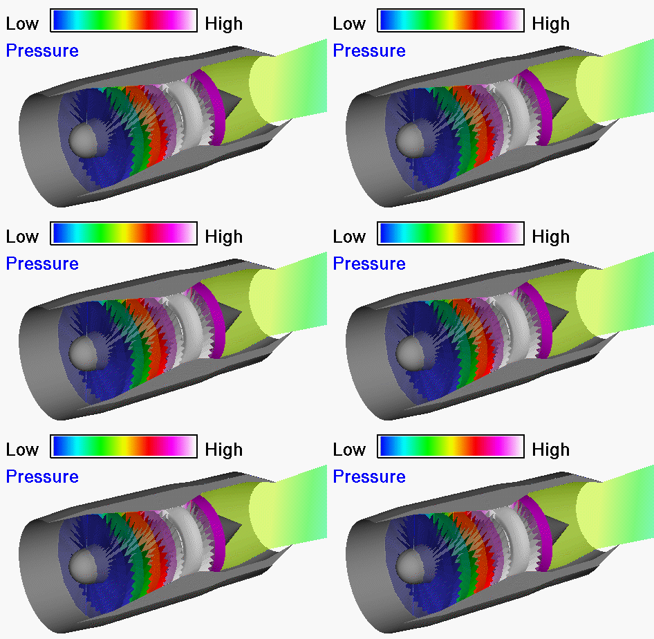
On this slide we show how the flow pressure varies through a typical turbojet engine. The pressure is color-coded, with blue indicating the lowest pressure and white the highest pressure. Air is brought into the turbojet through the inlet at the left of the computer drawing. At the rear of the inlet, the air enters the compressor. The compressor acts like many rows of airfoils, with each row producing a small increase in pressure. At the exit of the compressor, the air is at a much higher pressure than free stream. In the burner a small amount of fuel is combined with the air and ignited at near constant pressure. Leaving the burner, the hot exhaust is passed through the turbine. Energy is extracted from the flow by the turbine to turn the compressor, which is linked to the turbine by a central shaft. Some pressure is lost in the hot exhaust during this process, but the pressure entering the nozzle is still greater than free stream. The nozzle then converts the high pressure and temperature into high velocity. Because the exit velocity is greater than the free stream velocity, thrust is created as described by the thrust equation.
On a separate slide we discuss the computation of the engine pressure ratio which is defined to be the total pressure ratio across the engine. Using our station numbering system, EPR is the ratio of nozzle total pressure (pt8) to compressor face total pressure (pt2). EPR can be easily measured on an operating engine and displayed to the pilot on a cockpit dial. That is why the ratio is not defined in terms of free stream conditions. (Total pressure losses in the inlet are not contained in the EPR.) But if know EPR, the inlet losses, and the corresponding engine temperature ratio (ETR), we can easily compute the thrust of an engine using the nozzle performance information and the thrust equation. The EPR is simply the product of the pressure ratio across all of the engine components. For a given engine design, we can determine the pressure ratio of each component as given on each of the component thermodynamic slides.
Go to...
byTom
Benson
Please send suggestions/corrections to: benson@grc.nasa.gov