Electrical circuits are used throughout aerospace engineering,
from flight control systems, to cockpit instrumentation, to engine
control systems, to
wind tunnel
instrumentation and operation.
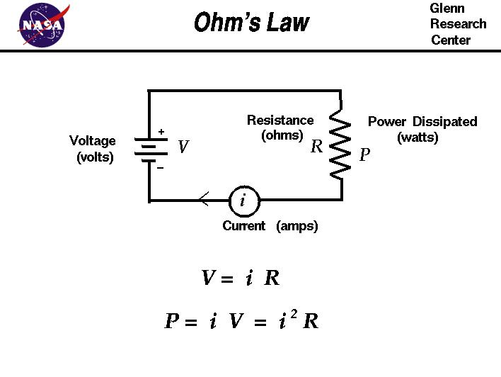
The most basic circuit involves a single resistor
and a source of electric potential or voltage. Electrons flow through
the circuit producing a current of electricity. The resistance,
voltage, and current are related to one another by
Ohm's law, as shown in the figure.
If we denote the resistance by R, the current by i, and the voltage by
V, then Ohm's law states that:
V = i R
Resistance is a circuit property that offers opposition to the flow of electrons
through a wire. It is analogous to friction in a mechanical system or aerodynamic
drag. The resistance is measured in ohms and depends on
the geometry of the resistor and the material used in the resistor. At the atomic level,
free electrons in a material are in constant random motion continually colliding
with one another and the surrounding atoms of the material.
When an electric field is applied, the electrons preferentially move
in the direction opposite to the field. The atoms form a matrix through which the electrons
move. Depending on the spacing, size, and orientation of the matrix, the speed of the flow
of electrons will vary. Different materials have different values of electrical conductivity.
The resistivity of the material is the inverse of the conductivity and denoted by rho.
If the material has a length l and a cross-sectional area A, the resistance is
given by:
R = (rho * l ) / A
As the electrons move through the material colliding with each other and with the atomic matrix,
the electrons generate random thermal energy or heat. Because of the random nature of the motion,
the collisions are irreversible and generate an increase in
entropy
as described in the second law of thermodynamics. The irreversible generation of heat by the resistor
dissipates power from the circuit. The power P is measured in watts and is given by:
P = i V = i^2 R
A resistor therefore carries two ratings: 1) its ohmic value, and 2) its power dissipation ability.
Because the resistance depends on the geometry of the resistor or wire, and the geometry
can be changed by an applied force, we can construct an electric circuit
for detecting forces using the change in resistance. Electric
strain gages are one of the most common types
of instruments used in
wind tunnel testing.
When building a practical circuit, there is normally more than one resistor. The resistors
may be connected in
parallel or in
series with a power source. A special circuit called the
Wheatstone bridge is used in wind tunnel testing to
eliminate temperature bias in strain gages.
Activities:

Navigation ..

- Beginner's Guide Home Page
|