
|
REL-ROT-ZONE ZONE iz1 BOUNDARY {I1 | IMAX | J1 | JMAX | K1 | KMAX} \ [SUBSET I range J range K range] ZONE iz2 BOUNDARY {I1 | IMAX | J1 | JMAX | K1 | KMAX} \ [SUBSET I range J range K range] ROTATING-ZONE AVERAGE [ABOUT] {X | Y | Z} \ [AREA | MIXED-OUT] [GILES] [AXIAL | RADIAL] ENDRRZ |
For structured grids, the REL-ROT-ZONE keyword block, along with the ROTATE keyword, may be used to specify that one zone is rotating relative to another zone. This "relative rotating zone" capability is intended to simulate rotating devices such as compressor fans.
The ROTATE keyword is used to specify which zone(s) are rotating, plus the center of rotation and rotation rate. The REL-ROT-ZONE keyword block specifies the location of the interface between the two zones, and how flow conditions are to be transferred between zones. Note that each pair of relative rotating zones must appear in its own REL-ROT-ZONE block.
Zones sharing an interface may have different circumferential extents. Thus, when modeling a turbomachinery component like a compressor, only one blade per stage is required. Multiple zones and zonal interfaces may be used to cover the radial extent of the stage-to-stage interface, but a single zone must be used in the circumferential direction. The interface between zones must correspond to a surface of revolution, and grid lines in the circumferential direction must be at a constant radius relative to the rotation axis. The rotation axis must correspond to a coordinate axis.
As noted above, this capability is intended to simulate rotating devices such as compressor fans. A typical configuration would be an upstream non-rotating zone covering the full 360° cross-section, and a rotating downstream zone (or zones, if multiple zones are used in the radial direction) with a circumferential extent of 360°/N corresponding to a single blade. Periodic boundary conditions would be set at the circumferential boundaries in the rotating zone(s), using GMAN's rotational coupling mode.
The coupling of the downstream face of the non-rotating zone to the upstream face of the rotating zone would also be done using GMAN's rotational coupling mode, repeated N - 1 times. This will couple all the points except for that portion of the face that corresponds to the downstream zone in its non-rotated position. These remaining points are then coupled using ordinary (i.e., non-rotated) coupling mode. [In Wind-US, non-zero rotation angles trigger the use of a rotationally periodic boundary condition. Since this is not what is wanted between two relative rotating zones, this "non-rotated" coupling should be done last, so that zero rotation angles are written into the common grid (.cgd) file.]
The elements of the REL-ROT-ZONE keyword block are defined as
follows:
| REL-ROT-ZONE |
Defines the beginning of the relative rotating zone block.
|
ZONE iz1 BOUNDARY {I1 | IMAX | J1 | JMAX | K1 | KMAX} \ [SUBSET I range J range K range] ZONE iz2 BOUNDARY {I1 | IMAX | J1 | JMAX | K1 | KMAX} \ [SUBSET I range J range K range] |
These two lines define the interface between the two zones. The relevant zones are given by the values of iz1 and iz2, and the relevant boundaries within zones iz1 and iz2 are specified via the BOUNDARY keyword parameter.
| iz1 | Zone to which increments will be added when passing information to iz2 | ||
|---|---|---|---|
| iz2 | Zone receiving positive increments, increments will be subtracted when passing information back to zone iz1 |
The SUBSET parameter may be used to specify that the change in properties occurs only over a portion of the zone boundary. Otherwise, it is assumed that the change occurs over the entire boundary. The range parameters define the part of the zone boundary over which the change occurs, and take one of the following forms:
| index1 index2 | Starting and ending indices in the specified direction. LAST may be used for the last index. | ||
|---|---|---|---|
| ALL | Equivalent to 1 LAST. |
The starting and ending indices for the appropriate
I, J, or K parameter
(depending on the boundary specified)
must be the same, and correspond to that boundary.
|
ROTATING-ZONE AVERAGE [ABOUT] {X | Y | Z} \ [AREA | MIXED-OUT] [GILES] [AXIAL | RADIAL] |
When the relative-rotating-zone capability is used, flow conditions at each radial grid point are circumferentially averaged before sending them to the adjacent coupled zone. This averaging-plane approach permits the communication of the bulk fluid properties between zones, while maintaining radial distributions and the efficiency of local time stepping. The ROTATING-ZONE AVERAGE keyword defines the circumferential direction used for the averaging.
Note that since it is currently assumed that the axis of rotation aligns with one of the Cartesian coordinate axes, the circumferential direction specified with ROTATING-ZONE AVERAGE must be consistent with the rotation rate specified with with the ROTATE keyword.
Since flow properties are related nonlinearly, the average properties may not satisfy all characteristics of the original system (i.e., information is lost through the averaging process). The averaging scheme used will dictate which properties are preserved. Two averaging methods are available for use.
| AREA | Area averaging uses simple area-weighted integrations of the flow properties. It does not guarantee conservation of mass, momentum, or energy, but may be more stable for certain applications. This is the default setting. | ||
|---|---|---|---|
| MIXED-OUT | Mixed-out averaging uses a stream-thrust flux-average to conserve mass, momentum, and energy. The averaged values formally represent the uniform flow that would exist far downstream.. |
The GILES option activates a non-reflecting boundary treatment at the rotor-stator interface to reduce problems caused by coupling of averaged data from the "other" zone.
The AXIAL or RADIAL option may be used to specify
whether the REL-ROT-ZONE interface is oriented axially or
radially. The default is AXIAL.
| ENDRRZ |
Defines the end of the relative rotating zone block.
Example
The following figure shows a four-zone configuration. Zone 1 is non-rotating, and zones 2, 3, and 4 are rotating about the x-axis at 1680 radians/sec in the counter-clockwise direction. The figure shows the grid from the side in a θ-constant plane, and at the interface plane between the non-rotating and rotating zones, looking downstream. In both views, only every other grid point is shown.
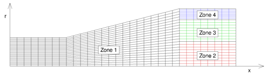
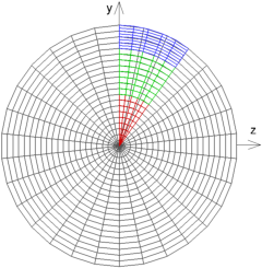
The non-rotating zone 1 covers the full 360° cross section, but the rotating zones 2-4 cover just 36°. As noted previously, zones sharing an interface may have different circumferential extents. This particular configuration is similar to one that might be used to model a single blade from a compressor blade row with 10 blades.
The indices i, j, and k are in the axial, radial, and circumferential directions, respectively. The table below summarizes the number of points used in each zone.
| Zone | imax | jmax | kmax |
|---|---|---|---|
| 1 | 49 | 43 | 61 |
| 2 | 17 | 19 | 11 |
| 3 | 17 | 17 | 11 |
| 4 | 17 | 17 | 11 |
For this configuration, the zone coupling was done in GMAN as described below. In this discussion, the "boundary zone" is the one containing grid points for which a boundary condition is being set. GMAN is used to set the connectivity between points in the boundary zone to points in the "source zone". The source zone is specified using GMAN's "SEL OTHER BND" menu choice.
Note that some users have reported difficulty inputting values to the GMAN prompts when the caps-lock and/or num-lock keys are active. Also note that GMAN only allows periodic coupling of an entire boundary surface, not a subset of that boundary. Certain grid topologies, such as C-grids and O-grids, may need to be split into multiple zones.
Here is the procedure for specifying the zone coupling with GMAN:
file relrotzone.cgd
switch
  1 (rotation mode)
   0.0 0.0 0.0 (rotation center)
  36.0 0.0 0.0 (rotation angles)
dR = R * ( 1 - cos( dθ / 2 ) )where dθ is the circumferential angle represented by the largest polygon face in the two zones. For this example,
dR = 2.0 * ( 1 - cos( 12° / 2 ) ) = 0.01096 ≈ 0.011This value will be used for the containment tolerance in the steps below.
0.011Once set, this value should remain in effect for all subsequent operations.
  1 (rotation mode)
   0.0 0.0 0.0 (rotation center)
  36.0 0.0 0.0 (rotation angles)
  1 (rotation mode)
   0.0 0.0 0.0 (rotation center)
  72.0 0.0 0.0 (rotation angles)
The steps above can also be accomplished with the following GMAN script.
   file relrotzone.cgd
   ZONE 1
     BOUNDARY IMAX
       UNDEFINED
       UPDATE
   ZONE 2
     BOUNDARY I1
       UNDEFINED
       UPDATE
   ZONE 3
     BOUNDARY I1
       UNDEFINED
       UPDATE
   ZONE 4
     BOUNDARY I1
       UNDEFINED
       UPDATE
   ZONE 1
     BOUNDARY K1
       COUPLED TO ZONE 1 BOUNDARY KMAX
       UPDATE
     BOUNDARY KMAX
       COUPLED TO ZONE 1 BOUNDARY K1
       UPDATE
   ZONE 2
     BOUNDARY K1
       CONNECTED TO ZONE 2 BOUNDARY KMAX ROTATION CENTER 0. 0. 0. ANGLES  36. 0. 0.
       UPDATE
     BOUNDARY KMAX
       CONNECTED TO ZONE 2 BOUNDARY K1   ROTATION CENTER 0. 0. 0. ANGLES -36. 0. 0.
       UPDATE
   ZONE 3
     BOUNDARY K1
       CONNECTED TO ZONE 3 BOUNDARY KMAX ROTATION CENTER 0. 0. 0. ANGLES  36. 0. 0.
       UPDATE
     BOUNDARY KMAX
       CONNECTED TO ZONE 3 BOUNDARY K1   ROTATION CENTER 0. 0. 0. ANGLES -36. 0. 0.
       UPDATE
   ZONE 4
     BOUNDARY K1
       CONNECTED TO ZONE 4 BOUNDARY KMAX ROTATION CENTER 0. 0. 0. ANGLES  36. 0. 0.
       UPDATE
     BOUNDARY KMAX
       CONNECTED TO ZONE 4 BOUNDARY K1   ROTATION CENTER 0. 0. 0. ANGLES -36. 0. 0.
       UPDATE
   ZONE 1
     BOUNDARY IMAX
       CONTAINMENT TOLERANCE 0.011
       CONNECTED TO ZONE 2 BOUNDARY I1 ROTATION CENTER 0. 0. 0. ANGLES  36. 0. 0.
       CONNECTED TO ZONE 2 BOUNDARY I1 ROTATION CENTER 0. 0. 0. ANGLES  72. 0. 0.
       CONNECTED TO ZONE 2 BOUNDARY I1 ROTATION CENTER 0. 0. 0. ANGLES 108. 0. 0.
       CONNECTED TO ZONE 2 BOUNDARY I1 ROTATION CENTER 0. 0. 0. ANGLES 144. 0. 0.
       CONNECTED TO ZONE 2 BOUNDARY I1 ROTATION CENTER 0. 0. 0. ANGLES 180. 0. 0.
       CONNECTED TO ZONE 2 BOUNDARY I1 ROTATION CENTER 0. 0. 0. ANGLES 216. 0. 0.
       CONNECTED TO ZONE 2 BOUNDARY I1 ROTATION CENTER 0. 0. 0. ANGLES 252. 0. 0.
       CONNECTED TO ZONE 2 BOUNDARY I1 ROTATION CENTER 0. 0. 0. ANGLES 288. 0. 0.
       CONNECTED TO ZONE 2 BOUNDARY I1 ROTATION CENTER 0. 0. 0. ANGLES 324. 0. 0.
       COUPLED TO ZONE 2 BOUNDARY I1
       UPDATE
       CONNECTED TO ZONE 3 BOUNDARY I1 ROTATION CENTER 0. 0. 0. ANGLES  36. 0. 0.
       CONNECTED TO ZONE 3 BOUNDARY I1 ROTATION CENTER 0. 0. 0. ANGLES  72. 0. 0.
       CONNECTED TO ZONE 3 BOUNDARY I1 ROTATION CENTER 0. 0. 0. ANGLES 108. 0. 0.
       CONNECTED TO ZONE 3 BOUNDARY I1 ROTATION CENTER 0. 0. 0. ANGLES 144. 0. 0.
       CONNECTED TO ZONE 3 BOUNDARY I1 ROTATION CENTER 0. 0. 0. ANGLES 180. 0. 0.
       CONNECTED TO ZONE 3 BOUNDARY I1 ROTATION CENTER 0. 0. 0. ANGLES 216. 0. 0.
       CONNECTED TO ZONE 3 BOUNDARY I1 ROTATION CENTER 0. 0. 0. ANGLES 252. 0. 0.
       CONNECTED TO ZONE 3 BOUNDARY I1 ROTATION CENTER 0. 0. 0. ANGLES 288. 0. 0.
       CONNECTED TO ZONE 3 BOUNDARY I1 ROTATION CENTER 0. 0. 0. ANGLES 324. 0. 0.
       COUPLED TO ZONE 3 BOUNDARY I1
       UPDATE
       CONNECTED TO ZONE 4 BOUNDARY I1 ROTATION CENTER 0. 0. 0. ANGLES  36. 0. 0.
       CONNECTED TO ZONE 4 BOUNDARY I1 ROTATION CENTER 0. 0. 0. ANGLES  72. 0. 0.
       CONNECTED TO ZONE 4 BOUNDARY I1 ROTATION CENTER 0. 0. 0. ANGLES 108. 0. 0.
       CONNECTED TO ZONE 4 BOUNDARY I1 ROTATION CENTER 0. 0. 0. ANGLES 144. 0. 0.
       CONNECTED TO ZONE 4 BOUNDARY I1 ROTATION CENTER 0. 0. 0. ANGLES 180. 0. 0.
       CONNECTED TO ZONE 4 BOUNDARY I1 ROTATION CENTER 0. 0. 0. ANGLES 216. 0. 0.
       CONNECTED TO ZONE 4 BOUNDARY I1 ROTATION CENTER 0. 0. 0. ANGLES 252. 0. 0.
       CONNECTED TO ZONE 4 BOUNDARY I1 ROTATION CENTER 0. 0. 0. ANGLES 288. 0. 0.
       CONNECTED TO ZONE 4 BOUNDARY I1 ROTATION CENTER 0. 0. 0. ANGLES 324. 0. 0.
       COUPLED TO ZONE 4 BOUNDARY I1
       UPDATE
   ZONE 2
     BOUNDARY I1
       COUPLED TO ZONE 1 BOUNDARY IMAX
       UPDATE
   ZONE 3
     BOUNDARY I1
       COUPLED TO ZONE 1 BOUNDARY IMAX
       UPDATE
   ZONE 4
     BOUNDARY I1
       COUPLED TO ZONE 1 BOUNDARY IMAX
       UPDATE
   LIST BOUNDARY CONDITION REPORT
   ZONE 3
    AUTOMATIC COUPLE FACE ZONE ALL
   LIST BOUNDARY CONDITION REPORT
The relevant keyword input in the input data (.dat) file would be
   ROTATE 0.0 0.0 0.0 -1680.0 0.0 0.0 ZONE 2:4

   REL-ROT-ZONE
      ZONE 1 BOUNDARY IMAX SUBSET I LAST LAST J  1   19 K ALL
      ZONE 2 BOUNDARY I1
      ROTATING-ZONE AVERAGE ABOUT X AREA AXIAL
   ENDRRZ
   REL-ROT-ZONE
      ZONE 1 BOUNDARY IMAX SUBSET I LAST LAST J 20   35 K ALL
      ZONE 3 BOUNDARY I1
      ROTATING-ZONE AVERAGE ABOUT X AREA AXIAL
   ENDRRZ
   REL-ROT-ZONE
      ZONE 1 BOUNDARY IMAX SUBSET I LAST LAST J 36 LAST K ALL
      ZONE 4 BOUNDARY I1
      ROTATING-ZONE AVERAGE ABOUT X AREA AXIAL
   ENDRRZ
See Also: ROTATE
Last updated 1 Apr 2016